Sony IPT-DS1 Operating Instructions - Page 49
Position marker C
 |
UPC - 027242777613
View all Sony IPT-DS1 manuals
Add to My Manuals
Save this manual to your list of manuals |
Page 49 highlights
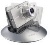
Place the plate on the base with the multi connector through the hole. ˎˎ The Sony logos on the main unit and plate should read in the same direction when the plate is attached to the main body. ˎˎ The plate and tilt arm have guide markers which should be aligned when attaching. On the plate: Position marker A ( ), position marker B ( ) On the tilt arm: Position marker C ( ) ˎˎ When placing the plate on the tilt arm, align the marker A ( ) on the plate with the marker C ( ) on the tilt arm. Position marker C ( ) Position marker A ( ) Slide the plate until the marker B ( ) on it is aligned with the marker C ( ) on the tilt arm. ˎˎ Make sure that the plate is properly seated. Position marker C ( ) Position marker B ( ) The plate clicks into place when inserted to the correct position. ˎˎ If it is slightly raised, remove it and repeat the above steps to attach it. 13-GB
-
 1
1 -
2
-
3
-
4
-
5
-
6
-
7
-
8
-
9
-
10
-
11
-
12
-
13
-
14
-
15
-
16
-
17
-
18
-
19
-
20
-
21
-
22
-
23
-
24
-
25
-
26
-
27
-
28
-
29
-
30
-
31
-
32
-
33
-
34
-
35
-
36
-
37
-
38
-
39
-
40
-
41
-
42
-
43
-
 44
44 -
 45
45 -
 46
46 -
 47
47 -
 48
48 -
 49
49 -
 50
50 -
 51
51 -
 52
52 -
 53
53 -
 54
54 -
55
-
56
-
57
-
58
-
59
-
60
-
61
-
62
-
63
-
64
-
65
-
66
-
67
-
68
-
69
-
70
-
71
-
72
-
73
-
74
-
75
-
76
-
77
-
78
-
79
-
80
-
81
-
82
-
83
-
84
-
85
-
86
-
87
-
88
-
89
-
90
-
91
-
92
-
93
-
94
-
95
-
96
-
97
-
98
-
99
-
100
-
101
-
102
-
103
-
104
-
105
-
106
-
107
-
108
-
109
-
110
-
111
-
112
-
113
-
114
-
115
-
116
-
117
-
118
-
119
-
120
-
121
-
122
-
123
-
124
-
125
-
126
-
127
-
128
-
129
-
130
-
131
 |
 |
