Sony KP-53S75 Operating Instructions - Page 14
Connecting a cable TV system/ antenna to a VCR, Connecting a VCR and projection TV to a cable box - power supply
 |
View all Sony KP-53S75 manuals
Add to My Manuals
Save this manual to your list of manuals |
Page 14 highlights
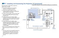
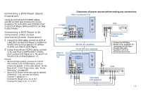
Installing and Connecting the Projection TV (continued) Connecting a cable TV system/ antenna to a VCR Disconnect all power sources before making any connections. (Rear of projection TV) 1 Attach the coaxial cable from the incoming cable connection or antenna to VHF/UHF IN on the VCR. 2 Using a coaxial cable, connect VHF/UHF OUT on the VCR to VHF/UHF on the projection TV. 3 Using AUDIO and S VIDEO* cables, connect AUDIO and S VIDEO OUT on the VCR to AUDIO and S VIDEO IN on the projection TV (White-AUDIO Left, Red- S VIDEO AUX TO CONVERTER Coaxial cable IN VIDEO 1 VIDEO 3 OUT VHF/UHF 2 S VIDEO VIDEO L (MONO) AUDIO R MONITOR AUDIO (VAR/FIX) Y VIDEO L PB (MONO) AUDIO PR R AUDIO R AUDIO L VIDEO LINE IN LINE OUT S VIDEO VCR VHF/UHF OUT IN COMPONENT 1 VIDEO VMC-810S/820S AUDIO-L AUDIO-R (not supplied) YC-15V/30V (not supplied) 3 Cable/ Antenna AUDIO Right**). Connecting a VCR and projection TV to a cable box 1 Connect the single (input) jack of the splitter to the incoming cable connection, and connect the other two (output) jacks (using the coaxial cable) to IN on the cable box and VHF/UHF on the projection TV. 2 Using a coaxial cable, connect OUT on the cable box to VHF/UHF IN on the VCR. 3 Using AUDIO and S VIDEO* cables, connect AUDIO and S VIDEO OUT on the VCR to AUDIO and S VIDEO IN on the projection TV (White-AUDIO Left, Red10AUDIO Right**). S VIDEO (Rear of projection TV) Coaxial cable AUX 1 TO CONVERTER Cable/ Antenna IN VIDEO 1 VIDEO 3 S VIDEO OUT MONITOR AUDIO (VAR/FIX) VIDEO Y VIDEO L (MONO) AUDIO R L PB (MONO) AUDIO PR R VHF/UHF Splitter (not supplied) AUDIO R AUDIO L VIDEO LINE IN LINE OUT S VIDEO VCR VHF/UHF OUT 2 IN COMPONENT VIDEO VMC-810S/820S AUDIO-L (not supplied) AUDIO-R YC-15V/30V (not supplied) 3 OUT IN Cable box
-
 1
1 -
2
-
3
-
4
-
5
-
6
-
7
-
8
-
 9
9 -
 10
10 -
 11
11 -
 12
12 -
 13
13 -
 14
14 -
 15
15 -
 16
16 -
 17
17 -
 18
18 -
 19
19 -
20
-
21
-
22
-
23
-
24
-
25
-
26
-
27
-
28
-
29
-
30
-
31
-
32
-
33
-
34
-
35
-
36
-
37
-
38
-
39
-
40
-
41
-
42
-
43
-
44
-
45
-
46
-
47
-
48
-
49
-
50
-
51
-
52
-
53
-
54
-
55
-
56
-
57
-
58
 |
 |
