Sony PCV-R556DS Reference Manual
Sony PCV-R556DS - Vaio Digital Studio Desktop Computer Manual
 |
View all Sony PCV-R556DS manuals
Add to My Manuals
Save this manual to your list of manuals |
Sony PCV-R556DS manual content summary:
- Sony PCV-R556DS | Reference Manual - Page 1
- Sony PCV-R556DS | Reference Manual - Page 2
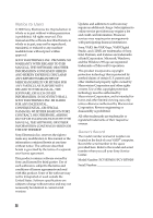
WITH REGARD TO THIS MANUAL, THE SOFTWARE, OR SUCH OTHER INFORMATION. IN NO EVENT SHALL SONY ELECTRONICS INC. BE LIABLE VAIO® computer. Record the serial number in the space provided here. Refer to the model and serial number when you call your Sony Service Center. Model Number: PCV-R556DS/PCV-R558DS - Sony PCV-R556DS | Reference Manual - Page 3
leak. ❑ The socket outlet shall be installed near the equipment and shall be easily accessible. ! To change the backup battery, contact your nearest Sony Service Center. ! Caution - The use of optical instruments with this product will increase eye hazard. As the laser beam used in this product is - Sony PCV-R556DS | Reference Manual - Page 4
de rechange, veuillez contacter votre centre de service Sony le plus près. ! Avertissement - L'utilisation désassembler le boîtier. Adressez-vous à un agent de service qualifié. ! Danger : Radiation laser visible et invisible si the Sony Service Center nearest you, call 1888-476-6972 in the United - Sony PCV-R556DS | Reference Manual - Page 5
SONY Model No.: PCV-R556DS/ PCV-R558DS Responsible Party: Sony Electronics Inc. Address: 1 Sony installed and used in accordance with the instructions, may cause harmful interference to radio changes or modifications not expressly approved in this manual could void your authority to operate this - Sony PCV-R556DS | Reference Manual - Page 6
the trouble is causing harm to the telephone network, the telephone company may request that you remove the equipment from the network until the problem is resolved. Repair of this equipment should be made only by a Sony Service Center or Sony authorized agent. For the Sony Service Center nearest - Sony PCV-R556DS | Reference Manual - Page 7
You can return your unwanted lithium ion batteries to your nearest Sony Service Center or Factory Service Center. ✍ In some areas the disposal of lithium ion by the manufacturer. Discard used batteries according to the manufacturer's instructions. ! The battery pack used in this device may present a - Sony PCV-R556DS | Reference Manual - Page 8
their own protection that the electrical ground connections of the power utility, telephone lines and internal metallic water pipe system é aux conditions énoncées cidessus n'empêche pas la dégradation du service dans certaines situations. Les réparations de matériel homologué doivent être coordonn - Sony PCV-R556DS | Reference Manual - Page 9
les régions rurales. Avertissement: L'utilisateur ne doit pas tenter de faire ces raccordements luimême; il doit avoir recours à un service d'inspection des installations électriques, ou à un électricien, selon le cas. AVIS: L'indice d'équivalence de la sonnerie (IES) assigné à chaque dispositif - Sony PCV-R556DS | Reference Manual - Page 10
x - Sony PCV-R556DS | Reference Manual - Page 11
View 2 Drives 3 Buttons and Switches 4 Indicators 5 Connectors 6 Rear View ...7 Icons ...8 I/O Connectors 10 Expansion Slots 14 Chapter 2 - Configuring Your System Accessing the BIOS Setup Utility 16 Changing the Display's Power Management Settings 17 Configuring the System Board 19 xi - Sony PCV-R556DS | Reference Manual - Page 12
xii VAIO Digital Studio™ Reference Manual Chapter 3 - Removing, Installing, and Replacing Components Drive 41 Removing the Power Supply 45 Replacing the Power Supply 48 Chapter 4 - System Board Connectors 50 Front Panel Header (J25 50 Diskette Drive Connector 51 Memory Module (DIMM) Connectors - Sony PCV-R556DS | Reference Manual - Page 13
Card Chapter 7 - CMOS Setup Options Main Screen 75 Advanced Screen 77 Power Screen 83 Boot Screen 85 Exit Screen 86 Chapter 8 - Miscellaneous Technical I/O Address Map 93 Memory Map 95 Chapter 9 - Specifications Processors 97 Chipset ...97 AGP Bus ...97 PCI Bus ...97 Memory Modules (DIMMs 97 - Sony PCV-R556DS | Reference Manual - Page 14
xiv - Sony PCV-R556DS | Reference Manual - Page 15
Chapter 1 Identifying Components The following sections identify and describe each component that is visible from the exterior of the VAIO Digital Studio™ Computer. Internal components are identified in the appropriate section of this manual. 1 - Sony PCV-R556DS | Reference Manual - Page 16
2 VAIO Digital Studio Reference Manual Front View Front panel OM04694X.VSD - Sony PCV-R556DS | Reference Manual - Page 17
Drives Identifying Components 3 DVD-ROM CD-RW Diskette drive FRNTPNLA.VSD Drive Diskette drive DVD-ROM drive* CD-RW drive† Description 3.5-inch, 1.44 Mbyte. DVD-ROM read: 16X (maximum performance). CD-ROM read: 40X (maximum performance). CD-RW read: 20X (maximum performance). CD-RW write: 4X ( - Sony PCV-R556DS | Reference Manual - Page 18
4 VAIO Digital Studio Reference Manual Buttons and Switches Optical disc eject Diskette eject Power/Standby FRNTPNLB.VSD Button or switch Power/Standby switch Diskette eject button Optical disc eject button Description Turns system power on, off, or into standby mode. Ejects a diskette. - Sony PCV-R556DS | Reference Manual - Page 19
Indicators Identifying Components 5 Optical drive access Diskette drive access Power/Standby Hard disk drive access FRNTPNLC.VSD Indicator Power/Standby indicator Diskette drive access indicator Optical drive access indicator Hard disk drive access indicator Description Standby (amber) - Sony PCV-R556DS | Reference Manual - Page 20
6 VAIO Digital Studio Reference Manual Connectors USB i.LINK FRNTPNLD.VSD Connector i.LINK® (IEEE-1394)* USB the i.LINK connector on the back of the system. A 6-pin i.LINK connector can supply power from the computer to the device if the device also has a 6-pin i.LINK connector. A 4-pin - Sony PCV-R556DS | Reference Manual - Page 21
Rear View Mouse Keyboard USB1, USB2 Ethernet Serial Printer/Parallel i.LINK (IEEE-1394) Game/MIDI Headphones LINE IN Microphone Monitor Line Identifying Components 7 Power Telephone KY0001.V - Sony PCV-R556DS | Reference Manual - Page 22
8 VAIO Digital Studio Reference Manual Icons Icon Icon label area OM04692X.VSD Description Mouse connector Keyboard connector Universal Serial Bus (USB) connector connector Headphones LINE IN jack (audio) Microphone jack Monitor connector Line jack (for telephone line from primary service jack) - Sony PCV-R556DS | Reference Manual - Page 23
Identifying Components 9 Icon Description Telephone jack (for phone) i.LINK (IEEE-1394) connector Ethernet connector - Sony PCV-R556DS | Reference Manual - Page 24
10 VAIO Digital Studio Reference Manual I/O Connectors The following section identifies the various I/O connectors. Keyboard and Mouse The keyboard and mouse connectors are physically identical and have the same pinout. They - Sony PCV-R556DS | Reference Manual - Page 25
Identifying Components 11 Serial Port The serial port is a standard 9-pin DB-9 male connector. 5 9 6 1 KY0057.VSD Printer/Parallel Port The printer/parallel port is a standard 25-pin DB-25 female connector. 13 25 14 1 KY0005.VSD Monitor The Monitor connector is a standard 15-pin female - Sony PCV-R556DS | Reference Manual - Page 26
12 VAIO Digital Studio Reference Manual Game Port The Game port is a standard 15-pin DB-15 female connector. This port is also used to connect MIDI devices. 8 15 9 1 KY0012.VSD - Sony PCV-R556DS | Reference Manual - Page 27
-1394) Connectors The 6-pin i.LINK connector on the back of the system can supply power from the computer to a device if the device also has a 6-pin i.LINK connector. The 6-pin connector supplies 10V to 12V and a maximum power of 6 watts. The 4-pin i.LINK connector at the bottom of the front panel - Sony PCV-R556DS | Reference Manual - Page 28
14 VAIO Digital Studio Reference Manual Expansion Slots There are three PCI slots, two of which are available for expansion. The other PCI slot is occupied by the fax/modem card (#1). AGP PCI #3 PCI #2 PCI #1 OM04577B.VSD - Sony PCV-R556DS | Reference Manual - Page 29
Chapter 2 Configuring Your System This chapter contains information on configuring your system. Configuring your system can consist of the following: ❑ Making changes to the BIOS settings ❑ Making changes to the display's power management settings ❑ Changing the system board jumper position 15 - Sony PCV-R556DS | Reference Manual - Page 30
16 VAIO Digital Studio Reference Manual Accessing the BIOS Setup Utility You must access the CMOS Setup Utility to make changes to the BIOS settings (see "CMOS Setup Options" on page 73 for information on BIOS settings). ! Before rebooting the system, save any open files and exit Windows®. 1 Reboot - Sony PCV-R556DS | Reference Manual - Page 31
Configuring Your System 17 Changing the Display's Power Management Settings A display that has power management capability is designed to operate on reduced power or shut itself off after the system has been idle for a specified period of time. 1 From the Start menu, point to Settings, then click - Sony PCV-R556DS | Reference Manual - Page 32
18 VAIO Digital Studio Reference Manual 5 Select the power scheme that is most appropriate for the way you use your computer. To change a power scheme, change the settings for System standby, Turn off monitor, and Turn off hard disks. The System standby option allows you to specify the period - Sony PCV-R556DS | Reference Manual - Page 33
The CMOS and Non-Volatile RAM (NVRAM) settings are only directed by a technical support or service technician. ! Before power of the computer and all attached peripherals, and unplug the power cord. 1 Remove the cover (see "Removing the Cover" on page 22). 2 Set the jumpers as directed by a service - Sony PCV-R556DS | Reference Manual - Page 34
20 - Sony PCV-R556DS | Reference Manual - Page 35
This chapter describes removing, installing, and replacing major components for upgrading, reconfiguring, and troubleshooting the components. ! Before opening the system unit, save any open files, exit Windows, turn off the power of the computer and all attached peripherals, and then unplug the - Sony PCV-R556DS | Reference Manual - Page 36
22 VAIO Digital Studio Reference Manual Removing the Cover You must remove the cover to access the system board, add-in cards, power supply, battery, memory, and internal drives. 1 From the rear of the unit, press the two tabs on the right side. 2 Remove the frame from the unit by gently - Sony PCV-R556DS | Reference Manual - Page 37
Removing, Installing, and Replacing Components 23 4 Lift the three-sided outer panel up and over the unit by pulling up on the large tab that extends from the top rear. KY0064A.VSD - Sony PCV-R556DS | Reference Manual - Page 38
24 VAIO Digital Studio Reference Manual Removing the Front Panel You must remove the front panel to install a 5¼" device. 1 Remove the cover (see "Removing the Cover" on page 22). 2 Push down - Sony PCV-R556DS | Reference Manual - Page 39
Removing, Installing, and Replacing Components 25 Replacing the Front Panel 1 Insert the two plastic tabs (located on the bottom of the front panel) into the slots at the bottom of the chassis. 2 Push the bottom of the front panel in until the tabs snap into place. 3 Push the top of the front - Sony PCV-R556DS | Reference Manual - Page 40
26 VAIO Digital Studio Reference Manual Replacing the Cover 1 Align the three-sided outer panel over the chassis and lower it onto the unit so that the tabs slip into the - Sony PCV-R556DS | Reference Manual - Page 41
Removing, Installing, and Replacing Components 27 5 Gently press the frame in until it clicks into position. KY0068.VSD - Sony PCV-R556DS | Reference Manual - Page 42
VAIO Digital Studio Reference Manual Installing an Add-In Card ! Before opening the system unit, save any open files, exit Windows, turn off the power of the computer and all attached peripherals, and then unplug the power cables to the card (see the instructions that came with the add-in card). - Sony PCV-R556DS | Reference Manual - Page 43
body may damage sensitive components on the card. As a precaution, touch any exposed metal part on the metal chassis (preferably the metal part on the power supply) before handling an add-in card to discharge any static electricity in your body. - Sony PCV-R556DS | Reference Manual - Page 44
30 VAIO Digital Studio Reference Manual 5 If you do not replace the card or install another add-in card, install a slot cover over the vacant slot at the rear of the chassis (see "Covering an Open I/O Slot" on page 40). 6 Replace the cover (see "Replacing the Cover" on page 26). - Sony PCV-R556DS | Reference Manual - Page 45
The lithium battery has a typical life of three years, after which the battery may be too weak to power the CMOS memory. ! When you remove the lithium battery, all values stored in the CMOS memory (BIOS setup values and Plug and Play values) may be lost. Although the computer can hold the charge for - Sony PCV-R556DS | Reference Manual - Page 46
VAIO Digital Studio Reference Manual battery and dispose of it according to the instructions that came with the new battery. 11 Insert the new battery the battery holder, with the plus (+) side up. ✍ The Sony CR2032 battery is recommended. Using a type of battery other than power cord and turn on the computer. - Sony PCV-R556DS | Reference Manual - Page 47
during the battery replacement and you can skip the remaining steps. 17 Refer to the list you made in step 3 and restore any non-default BIOS settings (see "CMOS Setup Options" on page 73). 18 Select Exit Saving Changes from the main menu using the right arrow key. 19 Press Enter - Sony PCV-R556DS | Reference Manual - Page 48
66 MHz or 100 MHz memory with 133 MHz memory. Supports SDRAM memory. Does not support EDO memory or buffered DIMM memory. 4 Disconnect the power cord from the computer. 5 Remove the cover (see "Removing the Cover" on page 22). 6 Remove the power supply (see "Removing the Power Supply" on page 45). - Sony PCV-R556DS | Reference Manual - Page 49
module and pin 1 on the socket. Press down here Handles Pin 1 side DIMM2 DIMM1 Memory module (DIMM) 1 8 Carefully but firmly insert the edge of the module into the socket into place. 10 Replace the power supply (see "Replacing the Power Supply" on page 48). 11 Replace the cover (see "Replacing the Cover" - Sony PCV-R556DS | Reference Manual - Page 50
36 VAIO Digital Studio Reference Manual 12 Reconnect the power cord and turn on the computer. Your computer automatically recognizes the extra memory and will configure itself accordingly when you turn on the computer. No further action is required. - Sony PCV-R556DS | Reference Manual - Page 51
and all attached peripherals, and then unplug the power cord. 13 Remove the cover (see "Removing the Cover" on page 22). 14 Locate the memory module you wish to remove. KY0073.VSD ✍ The memory modules are located beneath the power supply. You do not need to remove the power supply to reach the - Sony PCV-R556DS | Reference Manual - Page 52
38 VAIO Digital Studio Reference Manual 15 Reach around each side of the power supply and push down the handle on each side of the memory module to eject the module from its socket. Push out Handles KY00 16 Grasp one edge of the memory module and lift out. Store the module in a static-free bag. ! - Sony PCV-R556DS | Reference Manual - Page 53
and Replacing Components 39 Removing a Slot Cover You remove a slot cover when you install an add-in card that occupies a previously-empty slot. 1 Disconnect the power cord from the computer. 2 Remove the cover (see "Removing the Cover" on page 22). 3 Locate the slot whose cover you want to remove - Sony PCV-R556DS | Reference Manual - Page 54
40 VAIO Digital Studio Reference Manual Covering an Open I/O Slot Slot covers prevent air from escaping through the empty hole. If air escapes, the components inside the computer cannot be properly - Sony PCV-R556DS | Reference Manual - Page 55
. 1 Configure the jumpers on the new drive as a primary slave (see your drive's documentation for configuration instructions). Power connector Jumpers Drive connector KY0084.VSD 2 Disconnect the power cord from the computer. 3 Remove the cover (see "Removing the Cover" on page 22). 4 Remove the - Sony PCV-R556DS | Reference Manual - Page 56
42 VAIO Digital Studio Reference Manual 5 Slide the drive holder forward (B), and then out. A A A A Disk drive holder B KY0081.VSD 6 Place the drive holder on top of the power supply. 7 Slide the new drive into the drive holder and align the holes on each side of the drive holder. Align holes - Sony PCV-R556DS | Reference Manual - Page 57
Removing, Installing, and Replacing Components 43 10 Connect the second power connector to the new drive. Second power connector Second drive connector 11 Make sure the drive connector is connected securely to the motherboard. KY0085.VSD B B B B A KY0086.VSD 12 Lower the drive holder down - Sony PCV-R556DS | Reference Manual - Page 58
44 VAIO Digital Studio Reference Manual Your computer automatically recognizes the new drive and configures itself accordingly when you turn it on. Format and partition the new drive following the instructions provided with the drive. - Sony PCV-R556DS | Reference Manual - Page 59
Components 45 Removing the Power Supply You remove the power supply when you insert a memory module (see "Installing System Memory" on page 34). 1 Remove the three screws (A in next diagram) from the rear of the chassis. 2 Remove the screw (B) from the power supply bracket. A B KY0096.VSD - Sony PCV-R556DS | Reference Manual - Page 60
46 VAIO Digital Studio Reference Manual 3 Slide the power supply back (towards the 3½" drive bay) about ½" (or until the power supply detaches from the chassis tabs), then lift up until the power supply clears the chassis lip. KY0097.VSD - Sony PCV-R556DS | Reference Manual - Page 61
Removing, Installing, and Replacing Components 47 4 Rotate the power supply horizontally by 180 degrees counterclockwise and rest it on top of the chassis where the CDROM/DVD-ROM drive is located. KY0098.VSD - Sony PCV-R556DS | Reference Manual - Page 62
48 VAIO Digital Studio Reference Manual Replacing the Power Supply 1 Rotate the power supply horizontally by 180 degrees clockwise and lower it into the chassis until it is flush against the square hole at the rear of the chassis. 2 Slide the power supply forward (away from the 3½" drive bay) until - Sony PCV-R556DS | Reference Manual - Page 63
, i.LINK 1394 Header 2 Game Mic In, Line In, Line Out 1394 Header 3 CD-In Video Aux-In Processor CPU Fan Memory Slot 3 (PCI) Slot 2 (PCI) Slot 1 (PCI) Power Supply Fan Power Supply Secondary IDE Primary IDE Diskette AGP USB2 Header Battery Configuration Jumpers Front panel header OM04581.VSD 49 - Sony PCV-R556DS | Reference Manual - Page 64
50 VAIO Digital Studio Reference Manual Connectors Front Panel Header (J25) The front panel header is a 20- MSG LED PWR HD LED PWR RESET LED KY0031.VSD Description (not used) Connects to the power-on indicator light on the front panel Connects to the hard disk drive access light on the front panel - Sony PCV-R556DS | Reference Manual - Page 65
Diskette Drive Connector System Board 51 Key (pin 5) 33 1 34 2 OM04701H.VSD - Sony PCV-R556DS | Reference Manual - Page 66
52 VAIO Digital Studio Reference Manual Memory Module (DIMM) Connectors DIMM1 DIMM2 OM04710A.VSD Both sides of each Dual Inline Memory Module (DIMM) look very similar. The side with pin 1 has a small "1" to the left of pin 1. Be sure to orient a DIMM correctly in the DIMM - Sony PCV-R556DS | Reference Manual - Page 67
Board 53 PCI Slot Connectors There are a total of three PCI slot connectors (slot #1 to #3). Two PCI slots connector (#2 and #3) are available. The PCI slots support 32-bit 5V and Universal (3.3/5V) PCI add-in cards. Slot 3 (PCI) Slot 2 (PCI) Slot 1 (PCI) A1 A49 A52 A62 B1 B49 B52 B62 - Sony PCV-R556DS | Reference Manual - Page 68
54 VAIO Digital Studio Reference Manual AGP Connector There is one AGP slot connector that supports a 2x AGP graphics card or an AGP retention module. A1 A21 A26 B1 B21 B26 A66 B66 OM04599C.VSD - Sony PCV-R556DS | Reference Manual - Page 69
IDE and a Secondary IDE connector. Each IDE connector supports up to two IDE drives using a ribbon cable with two connectors. 40 39 2 1 OM04701G.VSD Power Connector The power supply connector on the system board connects to the power supply connector labelled P1. 10 20 1 11 OM04701I.VSD - Sony PCV-R556DS | Reference Manual - Page 70
56 VAIO Digital Studio Reference Manual Keyboard and Mouse Connectors The keyboard connector and the mouse connector are 6-pin female PS/2-type (mini-DIN) connectors. They have identical pinouts. Mouse 1 6 1 6 Keyboard - Sony PCV-R556DS | Reference Manual - Page 71
System Board 57 USB Connectors There are two USB ports at the rear panel, and one UBS port at the front panel. Each permits connection of USB peripheral devices directly to the system without having to use an external hub. USB2 and USB2 are standard USB connectors accessible from the rear panel. - Sony PCV-R556DS | Reference Manual - Page 72
58 VAIO Digital Studio Reference Manual USB1, USB2 connectors (continued) 5 USBVCC2* 6 USBP1# 7 USBP1 8 Ground * Uses over-current protector. Ethernet Connector There is one Ethernet connector at the rear panel, which permits - Sony PCV-R556DS | Reference Manual - Page 73
System Board 59 Serial 1, Printer, and i.LINK Connectors The Serial, Printer, and i.LINK connectors are mounted in a single bracket on the system board. The Serial 1 connector is a DB-9 male connector. The Printer connector is a DB-25 female connector. The i.LINK connector is a 6-pin standard IEEE - Sony PCV-R556DS | Reference Manual - Page 74
60 VAIO Digital Studio Reference Manual Printer connector Pin Signal Name 1 STROBE 2 DATA BIT 0 3 DATA BIT 1 4 DATA BIT 2 5 DATA BIT 3 6 DATA BIT 4 7 DATA BIT 5 8 DATA BIT 6 9 DATA BIT 7 10 ACK 11 - Sony PCV-R556DS | Reference Manual - Page 75
PWR-FAN connectors are 1 x 3-pin straight header connectors. CPU-FAN controls the cooling fan on the CPU. PWR-FAN controls the cooling fan in the power supply. CPU-FAN 3 1 PWR FAN 3 1 CPU-FAN and PWR-FAN connectors Pin Signal Name 1 Ground 2 FAN_CTRL (+12V) 3 FAN_SEN KY0034.VSD - Sony PCV-R556DS | Reference Manual - Page 76
62 VAIO Digital Studio Reference Manual Game Connector The Game connector is a female DB-15 connector for connecting to a game controller/joystick or MIDI device. Game Game connector Pin Signal Name 1 - Sony PCV-R556DS | Reference Manual - Page 77
System Board 63 Headphones, Line In, Mic Connectors The Headphones jack is a stereo mini-jack (3.5 mm) that connects to headphones. The Line In jack is a stereo mini-jack (3.5 mm) that connects to a stereo audio source (not an audio source from a video device). The Mic In jack is a stereo mini- - Sony PCV-R556DS | Reference Manual - Page 78
64 VAIO Digital Studio Reference Manual i.LINK Header Connectors The system board has two i.LINK header connectors: 1394HEAD2 (1394HEAD2 and 1394HEAD3) Pin Signal Name 1 Shell Ground 2 Ground 3 TPA 4 TPB* 5 TPB 6 GroundTPB* 7 Ground 8 VP (Power)* * Uses over-current protection. KY0099.VSD - Sony PCV-R556DS | Reference Manual - Page 79
System Board 65 CD-IN Connector The CD-IN connector on the system board is a 1 x 4-pin header connector that connects to the CD-ROM/DVD-ROM drive's audio output connector. CD-IN 4 1 CD-IN connector Pin Signal Name 1 Left Line In 2 Ground 3 Ground 4 Right Line In KY0062.VSD - Sony PCV-R556DS | Reference Manual - Page 80
66 VAIO Digital Studio Reference Manual AUX-IN Connector The AUX-IN connector on the system board is a 1 x 4-pin header connector that connects to the CD-RW drive's audio output connector. AUX-IN 4 1 AUX-IN connector Pin Signal Name 1 Left Line In 2 Ground 3 Ground 4 Right Line In KY0062B.VSD - Sony PCV-R556DS | Reference Manual - Page 81
(do not change). The computer ships with CMOS Clear in the Normal position. Do not change the position of this jumper unless directed by a technical support person. Reserved (do not change) CMOS CLR 3 2 1 = default jumper 1-2 2-3 CMOS Clear Normal Clear OM04588.VSD - Sony PCV-R556DS | Reference Manual - Page 82
68 - Sony PCV-R556DS | Reference Manual - Page 83
Chapter 5 Fax/Modem Card The fax/modem card occupies PCI slot #1. There are two RJ-11 jacks: one to connect a telephone line, and one to connect a phone. Telephone Line KY0038.VSD Connectors Name Telephone Line Connector Type RJ-11 RJ-11 Description Connects to phone Connects to telephone - Sony PCV-R556DS | Reference Manual - Page 84
70 - Sony PCV-R556DS | Reference Manual - Page 85
Chapter 6 Video Card The video card occupies the AGP slot. The video card has a standard 15-pin high-density VGA-style connector on the front bracket, and a 26-pin header connector (not used). The video card has 16 Mbytes of SDRAM and has a 128-bit wide bus. Monitor KY0104.V 71 - Sony PCV-R556DS | Reference Manual - Page 86
72 - Sony PCV-R556DS | Reference Manual - Page 87
BIOS Setup Utility (see "Accessing the BIOS Setup Utility" on page 16). The Award BIOS setup has five menu items on the menu bar. These are: ❑ Main ❑ Advanced ❑ Power are shown without brackets directly below the default option in this guide. The available options are listed in the order they occur - Sony PCV-R556DS | Reference Manual - Page 88
74 VAIO Digital Studio™ Reference Manual Press F10 to save the changes and exit, or press Esc to discard the changes. Follow the on-screen prompts for other choices. The bottom of the screen presents a summary of the keys to use for navigation and control. - Sony PCV-R556DS | Reference Manual - Page 89
None] 360K, 5.25 in. 1.2M, 5.25 in. 720K, 3.5 in. 1.44M, 3.5 in. 2.88M, 3.5 in. Floppy 3 Mode Support [Disabled] Drive A Drive B Both Primary Master (see "IDE Sub-Menus" on page 76) Primary Slave (see "IDE Sub-Menus" on but Disk All but Disk/Keyboard All Errors No Error Installed Memory 128 MB - Sony PCV-R556DS | Reference Manual - Page 90
76 VAIO Digital Studio™ Reference Manual IDE Sub-Menus Type Translation Method* Cylinders† Heads† Sectors‡ CHS Capacity* Maximum LBA Capacity* [Auto] User Type HDD CD-ROM LS-120 ZIP-100 MO Other ATAPI None [LBA] Large Normal Match Partition Table Manual [ 1024] [255] [63] 8422MB 30735MB Multi- - Sony PCV-R556DS | Reference Manual - Page 91
2 Cache [Enabled] Disabled CPU Level 2 Cache ECC Check [Disabled] Enabled BIOS Update [Enabled] Disabled PS/2 Mouse Function Control [Auto] Enabled USB Legacy Support [Auto] Disabled Enabled OS/2 Onboard Memory > 64M [Disabled] Enabled Chip Configuration (see "Chip Configuration Sub-Menu - Sony PCV-R556DS | Reference Manual - Page 92
78 VAIO Digital Studio™ Reference Manual Chip Configuration Sub-Menu SDRAM Configuration SDRAM CAS Latency SDRAM RAS to CAS Delay SDRAM RAS Precharge Time SDRAM Cycle Time (Tras, Trc) SDRAM Page Closing Policy CPU Latency Timer CPC Graphics Video Memory Cache Mode AGP 4X Support Memory Hole At 15M- - Sony PCV-R556DS | Reference Manual - Page 93
CMOS Setup Options 79 I/O Device Configuration Sub-Menu Onboard AC97 Audio Controller [Enabled] Disabled Onboard 1394 Controller [Enabled] Disabled Onboard Lan Controller [Enabled] Disabled Onboard FDC Swap A & B [No Swap] Swap AB Floppy Disk Access Control [R/W] Read Only Onboard Serial - Sony PCV-R556DS | Reference Manual - Page 94
80 VAIO Digital Studio™ Reference Manual PCI Configuration Sub-Menu Slot 1 IRQ to Slot 3 IRQ PCI/VGA Palette Snoop PCI Latency Timer SYMBIOS SCSI BIOS USB Function VGA BIOS Sequence Onboard LAN Boot ROM [Auto] NA 3 4 5 7 9 10 11 12 14 15 [Disabled] Enabled [32] [Auto] Disabled [Enabled] Disabled [ - Sony PCV-R556DS | Reference Manual - Page 95
CMOS Setup Options 81 PCI/PNP IRQ Resource Exclusion Sub-Menu IRQ 3 Reserved [No/ICU] Yes IRQ 4 Reserved [No/ICU] Yes IRQ 5 Reserved [Yes] No/ICU IRQ 7 Reserved [No/ICU] Yes IRQ 9 Reserved [No/ICU] Yes IRQ 10 Reserved [No/ICU] Yes IRQ 11 Reserved [No/ICU] Yes IRQ 12 Reserved [No/ - Sony PCV-R556DS | Reference Manual - Page 96
82 VAIO Digital Studio™ Reference Manual Shadow Configuration Sub-Menu Video ROM BIOS Shadow C8000-CBFFF Shadow CC000-CFFFF Shadow D0000-D3FFF Shadow D4000-D7FFF Shadow D8000-DBFFF Shadow DC000-DFFFF Shadow [Enabled] Disabled [Disabled] Enabled [Disabled] Enabled [ - Sony PCV-R556DS | Reference Manual - Page 97
Max Saving Video Off Option [Suspend -> Off] Always On Video Method [DPMS OFF] DPMS Reduce ON Blank Screen V/H SYNC+Blank DPMS Standby DPMS Suspend HDD Power Down [Disabled] 1 Min 2 Min 3 Min 4 Min 5 Min 6 Min 7 Min 8 Min 9 Min 10 Min 11 Min 12 Min 13 Min 14 Min 15 Min ACPI Mode - Sony PCV-R556DS | Reference Manual - Page 98
84 VAIO Digital Studio™ Reference Manual Power Up Control Sub-Menu AC PWR Loss Restart PWR Up On Modem Act Wake On LAN Hardware Monitor Sub-Menu MB Temperature CPU Temperature CPU Fan Speed Power Fan Speed VCORE Voltage +3.3V Voltage +5V Voltage +12V Voltage -12V Voltage -5V Voltage [Disabled] - Sony PCV-R556DS | Reference Manual - Page 99
Boot Screen 1. ATAPI CD-ROM 2. Removable Device 3. IDE Hard Drive 4. Other Boot Device Plug & Play O/S Boot Virus Detection Quick Power On Self Test Boot Up Floppy Seek Silent Boot CMOS Setup Options 85 [(displays installed drive)] Disabled [Legacy Floppy] LS120 ZIP-100 ATAPI MO Disabled [( - Sony PCV-R556DS | Reference Manual - Page 100
86 VAIO Digital Studio™ Reference Manual Exit Screen Exit Saving Changes Exit Discarding Changes Load Setup Defaults Discard Changes Save Changes - Sony PCV-R556DS | Reference Manual - Page 101
the following subjects: ❑ User and Supervisor password ❑ Beep code error messages ❑ PCI configuration status and error messages ❑ DMA channel assignments ❑ IRQ assignments ❑ System I/O address map ❑ Memory map ❑ PCI configuration space map 87 - Sony PCV-R556DS | Reference Manual - Page 102
88 VAIO Digital Studio Reference Manual About User and Supervisor Passwords The system allows you to specify up to two passwords (a User password and a Supervisor password) in the CMOS Setup Utility. - Sony PCV-R556DS | Reference Manual - Page 103
short beep signifies that the system is OK. Other beep patterns signify errors. The number of beeps indicates the specific error that occurred. The Sony Online Support technical representative will need to know how many beeps your system produces if there is an error, so be sure to count the number - Sony PCV-R556DS | Reference Manual - Page 104
90 VAIO Digital Studio Reference Manual PCI Configuration Status and Error Messages The following is a Resource Conflict PCI Error Log is Full PCI I/O Port Conflict PCI IRQ Conflict PCI Memory Conflict Primary Boot Device Not Found Primary IDE Controller Resource Conflict Primary Input Device Not - Sony PCV-R556DS | Reference Manual - Page 105
Miscellaneous Technical Information 91 Static Device Resource Conflict System Board Device Resource Conflict A non-Plug and Play ISA card has requested a resource that is already in use. A non-Plug and-Play ISA card has requested a resource that is already in use. - Sony PCV-R556DS | Reference Manual - Page 106
VAIO Digital Studio Reference Manual DMA Channel Assignments This shows the factory default values. Windows 98 reassigns resources to best meet the needs of a particular configuration. DMA Channel 0 1 2 3 4 5 6 7 Default Assignment Open Open Standard diskette drive controller Open Direct Memory - Sony PCV-R556DS | Reference Manual - Page 107
0200 - 0207 0220 - 022F 0290 - 0297 0330 - 0331 Description Direct memory access controller Motherboard resources Programmable interrupt controller Motherboard resources Motherboard resources Motherboard resources System timer Motherboard resources Standard 101/102-Key or Microsoft Natural Keyboard - Sony PCV-R556DS | Reference Manual - Page 108
94 VAIO Digital Studio Reference Manual Address Range (hex) 0376 - 0376 0376 - 0376 0378 - 037F 03B0 - 03BB 03CO - 03DF 03F0 ECP printer port (LPT1) NVIDIA Riva TNT2 Pro (Sony-English) NVIDIA Riva TNT2 Pro (Sony-English) Motherboard resources Standard diskette controller Intel 82801AA bus master IDE - Sony PCV-R556DS | Reference Manual - Page 109
Miscellaneous Technical Information 95 Memory Map Address range 00000000 - 0009FFFF 000A0000 BIOS NVIDIA Riva TNT2 Pro (Sony-English) NVIDIA Riva TNT2 Pro (Sony-English) NVIDIA Riva TNT2 Pro (Sony-English) Not available System board extension for ACPI BIOS System board extension for ACPI BIOS Sony - Sony PCV-R556DS | Reference Manual - Page 110
96 - Sony PCV-R556DS | Reference Manual - Page 111
for the Sony PCV-R556DS/PCV-R558DS computer. Processors PCV-R556DS: 733 MHz Intel Pentium® III processor PCV-R558DS: 866 open) Memory Modules (DIMMs) Installed memory Maximum memory Voltage Pins SDRAM type 128 Mbytes PC-133 SDRAM (133 MHz) 256 Mbytes (128Mbytes in each socket) 3.3 V memory only - Sony PCV-R556DS | Reference Manual - Page 112
98 VAIO Digital Studio Reference Manual DIMM Configurations DIMM1* 0, 8, 16, 32, 64, 128 DIMM2* 0, 8, 16, 32, 64, 128 * The PCV-R556DS/PCV-R558DS is shipped with 128 MB. SDRAM is expandable to 256 MB. Computer SDRAM is unbuffered DIMM, specification Rev. 1.0 or later. Supports SDRAM memory. Does - Sony PCV-R556DS | Reference Manual - Page 113
using K56flex™ technology/V.90. Your phone service, online service, or Internet Service Provider may not support this technology or operate at this speed. port with ECP and EPP modes One (supports MIDI in/out or two joysticks - adapter cable not supplied) Two RJ-11 connectors (for line and - Sony PCV-R556DS | Reference Manual - Page 114
IDE hard drive* DVD-ROM drive† CD-RW drive‡ 82077-compatible (supports up to 2.88 MByte) 1.44 MByte 3.5-inch MFDD Supports up to four EIDE drives (supports PIO Mode 4 EIDE drives and Ultra DMA/66 Mode drives) PCV-R556DS: 30 GByte PCV-R558DS: 40 GByte DVD-ROM read: 16X (maximum performance). CD-ROM - Sony PCV-R556DS | Reference Manual - Page 115
98 AUX-IN connector 66 B battery - See lithium battery beep codes 89 BIOS Setup Utility See CMOS Setup Utility BIOS setup utility advanced screen 77 boot screen 85 exit screen 86 main screen 75 options 73 power screen 83 screens 73 BIOS specifications 100 C card modem 69, 71 CD-IN connector 65 CD-RW - Sony PCV-R556DS | Reference Manual - Page 116
102 VAIO Digital Studio Reference Manual D DIMM - See memory module diskette drive connector 51 display, power management 17 disposal of lithium 1394 - See i.LINK installing 3½" hard disk drive 41 add-in card 28 system memory 34 interference v J jumper - See system board K keyboard connector 56 L L2 - Sony PCV-R556DS | Reference Manual - Page 117
power connector 55 power management, configuring 17 printer connector 59 processor specifications 97 R radio interference v RAM - See Also system memory audio 98 BIOS 100 communications 99 drives and controllers 100 graphics 98 I/O and expansion slots 99 L2 cache 98 memory module 97 processor - Sony PCV-R556DS | Reference Manual - Page 118
104 VAIO Digital Studio Reference Manual mouse connector 56 PCI slot connectors 53 power connector 55 printer connector 59 Serial connector 59 USB connectors 57, 58 system I/O address map 93 system memory, installing 34 T Telephone Consumer Protection Act of 1991 vi TV interference v U USB
-
 1
1 -
 2
2 -
 3
3 -
 4
4 -
 5
5 -
 6
6 -
 7
7 -
8
-
9
-
10
-
11
-
12
-
13
-
14
-
15
-
16
-
17
-
18
-
19
-
20
-
21
-
22
-
23
-
24
-
25
-
26
-
27
-
28
-
29
-
30
-
31
-
32
-
33
-
34
-
35
-
36
-
37
-
38
-
39
-
40
-
41
-
42
-
43
-
44
-
45
-
46
-
47
-
48
-
49
-
50
-
51
-
52
-
53
-
54
-
55
-
56
-
57
-
58
-
59
-
60
-
61
-
62
-
63
-
64
-
65
-
66
-
67
-
68
-
69
-
70
-
71
-
72
-
73
-
74
-
75
-
76
-
77
-
78
-
79
-
80
-
81
-
82
-
83
-
84
-
85
-
86
-
87
-
88
-
89
-
90
-
91
-
92
-
93
-
94
-
95
-
96
-
97
-
98
-
99
-
100
-
101
-
102
-
103
-
104
-
105
-
106
-
107
-
108
-
109
-
110
-
111
-
112
-
113
-
114
-
115
-
116
-
117
-
118
 |
 |