Sony PCV-RX755 System Reference Manual - Page 50
Replacing the Power Supply, Replacing the Side Panel - front panel connector
 |
View all Sony PCV-RX755 manuals
Add to My Manuals
Save this manual to your list of manuals |
Page 50 highlights
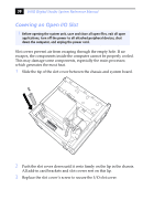
36 VAIO Digital Studio System Reference Manual 9 Align the module over the appropriate socket, noting the location of pin 1 on the module and pin 1 on the socket. Latch Edge Connector 10 Carefully but firmly insert the edge of the module into the socket. 11 Press down firmly and evenly at both corners until the module is fully seated. ✍ When the module is fully seated, the handles on each side are straight up and locked into the slot on each side of the module. If the handles are not totally straight upright, continue to press down on each side of the module until the handles lock into place. 12 Replace the AGP card and secure using the screw removed earlier. ✍ Be sure to press down firmly until the handle on the AGP slot is straight up and locked into the slot on the AGP card. 13 Replace the power supply (see "Replacing the Power Supply" on page 45). 14 Replace the side panel (see "Replacing the Side Panel" on page 25). 15 Reconnect the power cord and turn on the computer. Your computer automatically recognizes the extra memory and configures itself accordingly when you turn on the computer. No further action is required.
-
 1
1 -
2
-
3
-
4
-
5
-
6
-
7
-
8
-
9
-
10
-
11
-
12
-
13
-
14
-
15
-
16
-
17
-
18
-
19
-
20
-
21
-
22
-
23
-
24
-
25
-
26
-
27
-
28
-
29
-
30
-
31
-
32
-
33
-
34
-
35
-
36
-
37
-
38
-
39
-
40
-
41
-
42
-
43
-
44
-
 45
45 -
 46
46 -
 47
47 -
 48
48 -
 49
49 -
 50
50 -
 51
51 -
 52
52 -
 53
53 -
 54
54 -
 55
55 -
56
-
57
-
58
-
59
-
60
-
61
-
62
-
63
-
64
-
65
-
66
-
67
-
68
-
69
-
70
-
71
-
72
-
73
-
74
-
75
-
76
-
77
-
78
-
79
-
80
-
81
-
82
-
83
-
84
-
85
-
86
-
87
-
88
-
89
-
90
-
91
-
92
-
93
-
94
-
95
-
96
 |
 |
