Sony PCV-RX755 System Reference Manual - Page 61
System Board - front header
 |
View all Sony PCV-RX755 manuals
Add to My Manuals
Save this manual to your list of manuals |
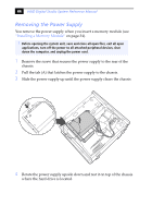
Page 61 highlights
Chapter 4 System Board This chapter identifies and describes components on the system board. Keyboard, Mouse CPU Fan Memory Stick Connector Processor Memory USB3, USB4 Ethernet Printer, i.LINK 1394 Header 3 Serial Port, Mic In, Line In Line Out CD-In (not used) Aux-In (not used) Slot No. 1 (CNR) Slot No. 2 (PCI) Slot No. 3 (PCI) Slot No. 4 (PCI) Aux Power Supply Power Supply Fan Power Supply Diskette Primary IDE Secondary IDE Battery CMOS Clear Front Panel Header USB23 Header Slot No. 5 (AGP) ✍ Your system board may vary, depending on the system configuration purchased. 47
-
 1
1 -
2
-
3
-
4
-
5
-
6
-
7
-
8
-
9
-
10
-
11
-
12
-
13
-
14
-
15
-
16
-
17
-
18
-
19
-
20
-
21
-
22
-
23
-
24
-
25
-
26
-
27
-
28
-
29
-
30
-
31
-
32
-
33
-
34
-
35
-
36
-
37
-
38
-
39
-
40
-
41
-
42
-
43
-
44
-
45
-
46
-
47
-
48
-
49
-
50
-
51
-
52
-
53
-
54
-
55
-
 56
56 -
 57
57 -
 58
58 -
 59
59 -
 60
60 -
 61
61 -
 62
62 -
 63
63 -
 64
64 -
 65
65 -
 66
66 -
67
-
68
-
69
-
70
-
71
-
72
-
73
-
74
-
75
-
76
-
77
-
78
-
79
-
80
-
81
-
82
-
83
-
84
-
85
-
86
-
87
-
88
-
89
-
90
-
91
-
92
-
93
-
94
-
95
-
96
 |
 |

47
Chapter 4
System Board
This chapter identifies and describes components on the system board.
✍
Your system board may vary, depending on the system configuration purchased.
Processor
Memory
Power Supply Fan
Aux Power Supply
Power Supply
Secondary IDE
Primary IDE
Diskette
Slot No. 5 (AGP)
Battery
Front Panel Header
USB23 Header
CMOS Clear
Slot No. 2 (PCI)
Slot No. 3 (PCI)
Slot No. 4 (PCI)
Keyboard, Mouse
USB3, USB4
1394 Header 3
Serial Port,
Mic In, Line In
CD-In
Aux-In
Printer, i.LINK
Ethernet
Line Out
CPU Fan
(not used)
Memory Stick Connector
Slot No. 1 (CNR)
(not used)