Sony PMW320K Product Manual (PMW320 Operating Instruction) - Page 23
Left side and upper SLOT SELECT S×S memory card
 |
View all Sony PMW320K manuals
Add to My Manuals
Save this manual to your list of manuals |
Page 23 highlights
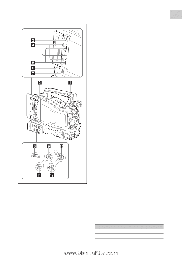
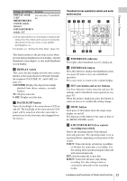
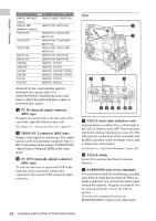
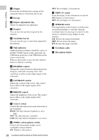
Chapter 1 Overview Left side and upper section HDMI GENLOCK IN VIDEO OUT TC OUT TC IN a ASSIGNABLE 4/5 switches You can assign the desired functions to these switches on OPERATION >Assignable SW in the setup menu (see page 132). Off is assigned to these switches when the camcorder is shipped from the factory. b USB connector Used to put this camcorder into USB connection mode and use it as an external storage device for a computer. When a computer without ExpressCard slot is connected to this connector, every memory card inserted in the camcorder is recognized as a drive for that computer. c S×S memory card slots These two slots (A and B) can receive S×S memory cards or other recording media (see page 67). d ACCESS lamps Indicate the state of slots A and B (see page 67). You can check whether the lamps are lit even when the slot cover is closed. e EJECT buttons To remove the recording media from the slot, press the EJECT button to release the lock, then press the button once more. This makes the media come out of the slot partially (see page 68). f Slot cover Slide to the left and right to open and close. g SLOT SELECT (S×S memory card select) button When S×S memory cards are loaded in both card slots A and B, press this button to select the card you want to use (see page 68). h HDMI output connector Outputs HDMI signals for video monitoring. When a video monitor provided with an HDMI signal input connector is connected to this connector, you can monitor picture being shot (camera picture) or playback picture. i GENLOCK IN (genlock signal input) connector (BNC type) This connector inputs a reference signal when the camcorder is to be genlocked or when timecode is to be synchronized with external equipment. Available reference signals vary depending on the current system frequency as shown in the following table. System frequency 1080/59.94i 1080/29.97P Available reference signals 1080/59.94i, 480/59.94i 1080/59.94i, 480/59.94i Locations and Functions of Parts and Controls 23
-
 1
1 -
2
-
3
-
4
-
5
-
6
-
7
-
8
-
9
-
10
-
11
-
12
-
13
-
14
-
15
-
16
-
17
-
 18
18 -
 19
19 -
 20
20 -
 21
21 -
 22
22 -
 23
23 -
 24
24 -
 25
25 -
 26
26 -
 27
27 -
 28
28 -
29
-
30
-
31
-
32
-
33
-
34
-
35
-
36
-
37
-
38
-
39
-
40
-
41
-
42
-
43
-
44
-
45
-
46
-
47
-
48
-
49
-
50
-
51
-
52
-
53
-
54
-
55
-
56
-
57
-
58
-
59
-
60
-
61
-
62
-
63
-
64
-
65
-
66
-
67
-
68
-
69
-
70
-
71
-
72
-
73
-
74
-
75
-
76
-
77
-
78
-
79
-
80
-
81
-
82
-
83
-
84
-
85
-
86
-
87
-
88
-
89
-
90
-
91
-
92
-
93
-
94
-
95
-
96
-
97
-
98
-
99
-
100
-
101
-
102
-
103
-
104
-
105
-
106
-
107
-
108
-
109
-
110
-
111
-
112
-
113
-
114
-
115
-
116
-
117
-
118
-
119
-
120
-
121
-
122
-
123
-
124
-
125
-
126
-
127
-
128
-
129
-
130
-
131
-
132
-
133
-
134
-
135
-
136
-
137
-
138
-
139
-
140
-
141
-
142
-
143
-
144
-
145
-
146
-
147
-
148
-
149
-
150
-
151
-
152
-
153
-
154
-
155
-
156
-
157
-
158
-
159
-
160
-
161
-
162
-
163
-
164
-
165
-
166
-
167
-
168
-
169
-
170
-
171
 |
 |