Sony STR-DE475 Operating Instructions - Page 10
Other Hookups - model
 |
View all Sony STR-DE475 manuals
Add to My Manuals
Save this manual to your list of manuals |
Page 10 highlights
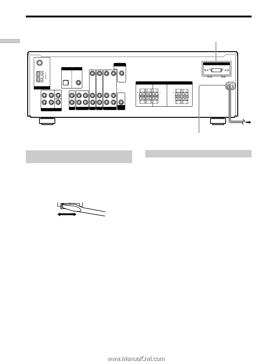
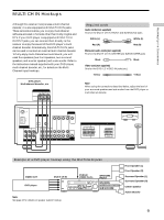
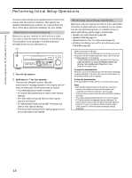
Hooking Up the Components Other Hookups VOLTAGE SELECTOR* FM 75Ω COAXIAL AM ANTENNA ANTENNA L DIGITAL TV/SAT IN DVD/LD IN OPTICAL CENTER L COAXIAL MONITOR VIDEO IN VIDEO IN VIDEO OUT VIDEO IN VIDEO OUT AUDIO OUT R SUB FRONT SURROUND WOOFER MULTI CH IN R IN CD OUT IN AUDIO IN AUDIO IN AUDIO OUT AUDIO IN SUB MD/TAPE TV/SAT DVD/LD VIDEO WOOFER SPEAKERS IMPEDANCE USE 8 - 16Ω SURROUND R L CENTER FRONT R L R L R L VOLTAGE SELECTOR 120V 240V 220V * Models of area code E2, E3 only. Setting the VOLTAGE SELECTOR (models of area code E2, E3 only) Check that the voltage selector on the rear panel of the player is set to the local power line voltage. If not, set the selector to the correct position using a screwdriver before connecting the AC power cord to a wall outlet. 120 V 240 V 220 V AC power cord To a wall outlet Connecting the AC power cord Before connecting the AC power cord of this receiver to a wall outlet: • Connect the speaker system to the receiver (see page 12). Connect the AC power cord(s) of your audio/video components to a wall outlet. Note If the AC power cord is disconnected for about one week, the receiver's entire memory will be cleared and the demonstration will start. 10
-
 1
1 -
2
-
3
-
4
-
 5
5 -
 6
6 -
 7
7 -
 8
8 -
 9
9 -
 10
10 -
 11
11 -
 12
12 -
 13
13 -
 14
14 -
 15
15 -
16
-
17
-
18
-
19
-
20
-
21
-
22
-
23
-
24
-
25
-
26
-
27
-
28
-
29
-
30
-
31
-
32
-
33
-
34
-
35
-
36
-
37
-
38
-
39
-
40
-
41
-
42
-
43
-
44
-
45
-
46
-
47
-
48
-
49
-
50
-
51
-
52
 |
 |