Sony STR-K7100 Service Manual - Page 54
Sony STR-K7100 - Multi Channel Av Receiver Manual
 |
View all Sony STR-K7100 manuals
Add to My Manuals
Save this manual to your list of manuals |
Page 54 highlights
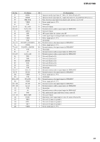
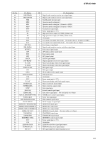
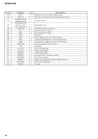
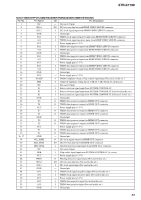
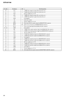
STR-K7100 Pin No. 54 55 56 57 58 59 60 61 62 63 64 65, 66 67 68 69 70 71 72 73 74 75 76 77 78 79 80 Pin Name B33 A33 VCC B34 A34 GND NC VCC HPD2 SDA2 SCL2 GND B21 A21 VCC B22 A22 GND B23 A23 VCC B24 A24 GND VCC HPD1 I/O Pin Description I TMDS data (negative) input (Not used in this set.) I TMDS data (positive) input (Not used in this set.) - Power supply pin (+3.3 V) I TMDS data (negative) input (Not used in this set.) I TMDS data (positive) input (Not used in this set.) - Ground pin - Not used. (Open) - Power supply pin (+3.3 V) O Hot plug detection signal output for HDMI DVD IN connector I/O I2C two-way data bus with HDMI DVD IN connector I I2C clock signal input from HDMI DVD IN connector - Ground pin I TMDS clock signal (negative) input from HDMI DVD IN connector I TMDS clock signal (positive) input from HDMI DVD IN connector - Power supply pin (+3.3 V) I TMDS data (negative) input from HDMI DVD IN connector I TMDS data (positive) input from HDMI DVD IN connector - Ground pin I TMDS data (negative) input from HDMI DVD IN connector I TMDS data (positive) input from HDMI DVD IN connector - Power supply pin (+3.3 V) I TMDS data (negative) input from HDMI DVD IN connector I TMDS data (positive) input from HDMI DVD IN connector - Ground pin - Power supply pin (+3.3 V) O Hot plug detection signal output for HDMI VIDEO 2/BD IN connector 54
-
 1
1 -
2
-
3
-
4
-
5
-
6
-
7
-
8
-
9
-
10
-
11
-
12
-
13
-
14
-
15
-
16
-
17
-
18
-
19
-
20
-
21
-
22
-
23
-
24
-
25
-
26
-
27
-
28
-
29
-
30
-
31
-
32
-
33
-
34
-
35
-
36
-
37
-
38
-
39
-
40
-
41
-
42
-
43
-
44
-
45
-
46
-
47
-
48
-
 49
49 -
 50
50 -
 51
51 -
 52
52 -
 53
53 -
 54
54 -
 55
55 -
 56
56 -
 57
57 -
 58
58 -
 59
59 -
60
-
61
-
62
-
63
-
64
-
65
-
66
-
67
-
68
-
69
-
70
-
71
-
72
-
73
-
74
 |
 |