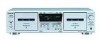
Sony WE475 Service Manual - Page 10
Bias Consumption Current Adjustment, DECK B, Record Bias Adjustment, Record Level Adjustment
 |
UPC - 027242584419
View all Sony WE475 manuals
Add to My Manuals
Save this manual to your list of manuals |
Page 10 highlights
TC-WE475 Bias Consumption Current Adjustment DECK B This adjustment should be performed when replacing the head assy or the bias oscillator transformer (T141, T241). Setting: REC LEVEL knob : standard recording position (See page 11.) Procedure: blank tape CS-413 digital voltmeter set LINE IN no signal R-CH L-CH 1 2 3 TP441 1. Connect the digital voltmeter to test point TP441. 2. Set RV141 (L-CH), RV241 (R-CH) to mechanical center. 3. Press the H button to playback. 4. Adjust T141 (L-CH), T241 (R-CH) so that the digital voltmeter reading becomes minimum. Adjustment Value: Maximum 220 mV Adjustment Location: MAIN board (See page 14.) Record Bias Adjustment DECK B Setting: REC LEVEL knob : standard record position (See page 11.) Procedure: 1. Set to test mode (See page 11.) 2. Insert a tape into deck B, press the REC z button and then press the H button to start recording. 3. Record Mode AF OSC attenuator 10 kΩ blank tape CS-123 set 600 Ω LINE IN 1) 315 Hz 2) 10 kHz 50 mV (-23.8 dBs) 4. Playback Mode recorded portion set level meter 47 kΩ LINE OUT 5. Confirm playback the signal recorded in step 2 become adjustment level as follows. If the selevels do not adjustment level, adjust the RV141 (L-CH) and RV241 (R-CH) to repeat steps 3 and 4. Adjustment level: The palyback output of 10 kHz level difference against 315 Hz reference should be ± 0.5 dB. Adjustment Location: MAIN board (See page 14.) 10 Record Level Adjustment DECK B Setting: REC LEVEL knob : standard record position (See page 11.) Procedure: 1. Set to test mode (See page 11.) 2. Insert a tspe into deck B, press the REC z button and then press the H button to start recording. 3. Record Mode AF OSC attenuator 10 kΩ blank tape CS-123 set 600 Ω LINE IN 315 Hz, 50 mV (-23.8 dBs) 4. Playback Mode recorded portion level meter 47 kΩ set LINE OUT 5. Confirm playback the signal recorded in step 2 become adjustment level as follows. If the selevels do not adjustment level, adjust the RV101 (L-CH) and RV201 (R-CH) to repeat steps 3 and 4. Adjustment Value: LINE OUT level : -23.8 dBs ± 0.5 dB (47.2 to 53.0 mV) Adjustment Location: MAIN board (See page 14.)
-
 1
1 -
2
-
3
-
4
-
 5
5 -
 6
6 -
 7
7 -
 8
8 -
 9
9 -
 10
10 -
 11
11 -
 12
12 -
 13
13 -
 14
14 -
 15
15 -
16
-
17
-
18
-
19
-
20
-
21
-
22
-
23
-
24
-
25
-
26
-
27
-
28
-
29
-
30
-
31
-
32
-
33
-
34
-
35
-
36
-
37
-
38
 |
 |
