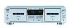
Sony WE475 Service Manual - Page 7
Tc-we475, Service Mode - tc s
 |
UPC - 027242584419
View all Sony WE475 manuals
Add to My Manuals
Save this manual to your list of manuals |
Page 7 highlights
SECTION 3 SERVICE MODE TC-WE475 KEY CHECK & DISPLAY CHECK MODE While pressing the h (A deck) and REC MUTING W buttons with the power off, press the POWER button to turn on the power. The fluorescent indicator tube displays the number or special message corresponding to the button pressed. The message displayed differs according to the position of the switch. RESET Button MEMORY m (AMS) (AMS) M x h H DIRECTION MODE switch g s RELAY A deck side Display 0 1 2 3 Grid check display (*1) 4 5 h PLAY H Button RESET MEMORY HIGH/NOMAL m (AMS) (AMS) M x h H PAUSE X REC MUTING W REC z FADER ARL SYNCHRO DOLBY NR switch OFF B C B deck side Display 0 1 2 3 4 Segment check display (*2) 5 6 7 8 9 A b All lit h PLAY H Grit check display (*1) RMS Segment check display (*2) 7
-
 1
1 -
 2
2 -
 3
3 -
 4
4 -
 5
5 -
 6
6 -
 7
7 -
 8
8 -
 9
9 -
 10
10 -
 11
11 -
 12
12 -
13
-
14
-
15
-
16
-
17
-
18
-
19
-
20
-
21
-
22
-
23
-
24
-
25
-
26
-
27
-
28
-
29
-
30
-
31
-
32
-
33
-
34
-
35
-
36
-
37
-
38
 |
 |
