Sony WE475 Service Manual - Page 3

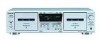
Electrical Parts List - tc cassette deck

Page 3 highlights

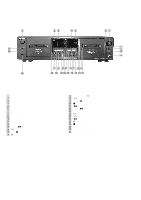
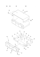
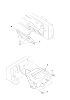
MODEL IDENTIFICATION -Back panel- Part No. PARTS No. 4-232-514-0s 4-232-514-1s 4-232-514-2s 4-232-514-3s 4-232-514-4s 4-232-514-5s MODEL US model CND model AEP model UK model SP model AUS model • Abbreviation CND : Canadian model SP : Singapore model AUS : Australian model TC-WE475 TABLE OF CONTENTS 1. GENERAL 4 2. DISASSEMBLY 2-1. Case 5 2-2. Front Panel Assy 5 2-3. Cassette Lid Assy (Deck A/B 6 2-4. Mechanism Deck Assy (Deck A/B 6 3. SERVICE MODE 7 4. MECHANICAL ADJUSTMENTS 8 5. ELECTRICAL ADJUSTMENTS 8 6. DIAGRAMS 6-1. Circuit Boards Location 12 6-2. Printed Wiring Board - MAIN Section 14 6-3. Schematic Diagram - MAIN (1/4) Section 15 6-4. Schematic Diagram - MAIN (2/4) Section 16 6-5. Schematic Diagram - MAIN (3/4) Section 17 6-6. Schematic Diagram - MAIN (4/4) Section 18 6-7. Printed Wiring Board - DECK A Section 19 6-8. Schematic Diagram - DECK A Section 19 6-9. Printed Wiring Board - DECK B Section 19 6-10. Schematic Diagram - DECK B Section 19 6-11. Schematic Diagram - DISPLAY Section 20 6-12. Printed Wiring Board - DISPLAY Section 21 6-13. Schematic Diagram - PANEL Section 22 6-14. Printed Wiring Board - PANEL Section 23 6-15. Schematic Diagram - POWER Section 24 6-16. Printed Wiring Board - POWER Section 25 6-17. IC PIN FUNCTION 26 7. EXPLODED VIEWS 7-1. Case Section 27 7-2. Chassis Section 28 7-3. Cassette Holder Section 29 7-4. Front Panel Section 30 7-5. Tape Mechanism Section 31 8. ELECTRICAL PARTS LIST 32 3

  • 1
  • 2
  • 3
  • 4
  • 5
  • 6
  • 7
  • 8
  • 9
  • 10
  • 11
  • 12
  • 13
  • 14
  • 15
  • 16
  • 17
  • 18
  • 19
  • 20
  • 21
  • 22
  • 23
  • 24
  • 25
  • 26
  • 27
  • 28
  • 29
  • 30
  • 31
  • 32
  • 33
  • 34
  • 35
  • 36
  • 37
  • 38

3
TC-WE475
PARTS No.
MODEL
4-232-514-0
s
US model
4-232-514-1
s
CND model
4-232-514-2
s
AEP model
4-232-514-3
s
UK model
4-232-514-4
s
SP model
4-232-514-5
s
AUS model
MODEL IDENTIFICATION
–Back panel–
Part No.
• Abbreviation
CND
: Canadian model
SP
: Singapore model
AUS
: Australian model
TABLE OF CONTENTS
1. GENERAL
..........................................................................
4
2. DISASSEMBLY
2-1. Case
......................................................................................
5
2-2.
Front Panel Assy
...................................................................
5
2-3. Cassette Lid Assy (Deck A/B)
..............................................
6
2-4. Mechanism Deck Assy (Deck A/B)
......................................
6
3. SERVICE MODE
..............................................................
7
4. MECHANICAL ADJUSTMENTS
.................................
8
5. ELECTRICAL ADJUSTMENTS
.................................
8
6. DIAGRAMS
6-1. Circuit Boards Location
......................................................
12
6-2. Printed Wiring Board – MAIN Section –
............................
14
6-3. Schematic Diagram – MAIN (1/4) Section –
......................
15
6-4. Schematic Diagram – MAIN (2/4) Section –
......................
16
6-5. Schematic Diagram – MAIN (3/4) Section –
......................
17
6-6. Schematic Diagram – MAIN (4/4) Section –
......................
18
6-7. Printed Wiring Board – DECK A Section –
........................
19
6-8. Schematic Diagram – DECK A Section –
...........................
19
6-9. Printed Wiring Board – DECK B Section –
........................
19
6-10. Schematic Diagram – DECK B Section –
.........................
19
6-11. Schematic Diagram – DISPLAY Section –
.......................
20
6-12. Printed Wiring Board – DISPLAY Section –
....................
21
6-13. Schematic Diagram – PANEL Section –
...........................
22
6-14. Printed Wiring Board – PANEL Section –
........................
23
6-15. Schematic Diagram – POWER Section –
.........................
24
6-16. Printed Wiring Board – POWER Section –
......................
25
6-17. IC PIN FUNCTION
..........................................................
26
7. EXPLODED VIEWS
7-1. Case Section
........................................................................
27
7-2. Chassis Section
...................................................................
28
7-3. Cassette Holder Section
......................................................
29
7-4. Front Panel Section
.............................................................
30
7-5. Tape Mechanism Section
....................................................
31
8. ELECTRICAL PARTS LIST
........................................
32