TEAC AX-505 Owners Manual English Francais Espanol - Page 10
Main unit parts and functions
 |
View all TEAC AX-505 manuals
Add to My Manuals
Save this manual to your list of manuals |
Page 10 highlights
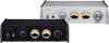
Main unit parts and functions A B C DE F A STANDBY/ON switch Use to put the unit into standby mode or turn it on. B PHONES jack Connect headphones with a 3.5mm (1/8") stereo mini plug here (page 9). oo This headphone amp circuit uses a four-pole connector with independent left and right for grounding. Ordinary plugs with 3 or 4 poles can be used. oo When headphones are connected to this unit, sound will be output from the PHONES jack but will not be output from the SPEAKERS terminals on the back of the unit. Wiring illustration C INPUT SELECTOR knob Use to select the input source. The indicator lights for the selected source. D Remote control signal receiver This receives signals from the remote control. When operating the remote control, point it at the remote control signal receiver. E Level meters These show the output levels. F VOLUME knob Use to adjust the volume. Turn right to increase and left to decrease the volume. L+ R+ L− R− The maximum volume level is 0 and the minimum level is −∞ (negative infinity). Before setting the STANDBY/ON switch to ON, set the VOLUME knob to its minimum value (−∞). Failure to do so could result in sudden loud noises that could damage speakers and harm your hearing. 10
-
 1
1 -
2
-
3
-
4
-
 5
5 -
 6
6 -
 7
7 -
 8
8 -
 9
9 -
 10
10 -
 11
11 -
 12
12 -
 13
13 -
 14
14 -
 15
15 -
16
-
17
-
18
-
19
-
20
-
21
-
22
-
23
-
24
-
25
-
26
-
27
-
28
-
29
-
30
-
31
-
32
-
33
-
34
-
35
-
36
-
37
-
38
-
39
-
40
-
41
-
42
-
43
-
44
-
45
-
46
-
47
-
48
 |
 |
