TEAC IF-SM/DM IF-SM:DM Owner's Manual - Page 4
Introduction : Connections
 |
View all TEAC IF-SM/DM manuals
Add to My Manuals
Save this manual to your list of manuals |
Page 4 highlights
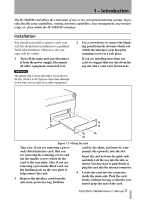
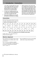
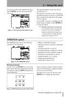
1 - Introduction : Connections A new unit's card slot and/or new card may be a little stiff. Make sure that the card is pushed as far as it will go (so that the card rear connector plate touches the rear panel of the unit). 5 Use the screws supplied with the card to attach the rear panel of the interface card to the rear panel of the unit. 6 Repeat the installation process for all the interface cards that you are fitting. • When removing a card, unscrew the five retaining screws and use the "pull posts" on the rear panel of the card to remove it from the unit. There are no rules governing which interface cards may be fitted in any of the slots, except for the IF-FW card, which must be fitted in slot 1-any other interface card may be fitted in any expansion slot. Connections The D-sub 25-pin connector allows the connection of up to eight balanced analog connections at +4dBu levels (the impedance is 100Ω). Pin 1 2 3 4 5 6 7 8 9 10 11 12 13' 8+ 8Gnd 7- 6+ 6Gnd 5- 4+ 4Gnd 3- 2+ 2Gnd 1- NC Signal 8- 7+ 7Gnd 6- 5+ 5Gnd 4- 3+ 3Gnd 2- 1+ 1Gnd Pin 14 15 16 17 18 19 20 21 22 23 24 25 Table 1.2: Pin assignments of the IF-SM/DM analog outputs Suitable cables can be obtained from most professional audio suppliers. Monitor alignment The card allows each channel to have an individual delay time set in milliseconds, as well as a trim level. This is set using the MONITOR ALIGNMENT screen, and the procedure is described later in this manual ("MONITOR ALIGNMENT option" on page 14). The overall SPL level can be set (on the OPERATION screen), along with the LFE gain. 4 TASCAM IF-SM/DM Owner's Manual
-
 1
1 -
 2
2 -
 3
3 -
 4
4 -
 5
5 -
 6
6 -
 7
7 -
 8
8 -
 9
9 -
 10
10 -
11
-
12
-
13
-
14
-
15
-
16
-
17
-
18
-
19
 |
 |
