TEAC IF-SM/DM IF-SM:DM Owner's Manual - Page 7
Using the card : ROUTING option
 |
View all TEAC IF-SM/DM manuals
Add to My Manuals
Save this manual to your list of manuals |
Page 7 highlights
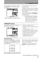
2 - Using the card : ROUTING option Notes on other hardware controls MONO key When the card is being used for monitoring in surround mode, the MONO key on the control surface is used to turn downmix on and off (as set up in DOWN MIX). ROUTING option There are two main functions here. The first allows you to set up the monitoring keys, and DIM key The DIM key on the control surface can be used in the usual way to dim the outputs from the card. The dimming level is set in the mixer. the second allows assignment of the outputs to the different channels. Figure 2.4: ROUTING option screen Monitoring keys The three assignable monitor selection hardware keys in the mixer's monitoring section can be set here. The following can be selected as monitor sources (stereo): • Individual Aux busses • Pairs of Aux busses • Individual busses • Pairs of busses • Digital inputs (1 or 2) • 2 TR analog inputs • The TDIF signals (1 through 3) Output routing When a "Line" is referred to in this screen, it is referring to the analog output line from the IFSM/DM card (as shown in Table 1.2, Pin assignments of the IF-SM/DM analog outputs).. The lines can be assigned to the different channels used by the surround pattern currently selected, differing from the default assignments made when the surround pattern is selected. • The ADAT signal • The signal of any card in a slot other than the surround monitor card In LRCS, 5.1 or 6.1 modes: • Surround buss 1-8 • Surround buss 9-16 • Digital inputs (1 or 2) • The TDIF signals (1 through 3) • The ADAT signal • The signal of any card in a slot other than the surround monitor card These channels are shown as L, R, C, etc. If a line output is unused by the pattern, as output 8 is unused in Figure 2.4, ROUTING option screen, it is shown with the number and dashes (-8-). Note that loopback routing is not possible in this case (see Figure 3.2, Level diagram). TASCAM IF-SM/DM Owner's Manual 7
-
 1
1 -
 2
2 -
 3
3 -
 4
4 -
 5
5 -
 6
6 -
 7
7 -
 8
8 -
 9
9 -
 10
10 -
 11
11 -
 12
12 -
13
-
14
-
15
-
16
-
17
-
18
-
19
 |
 |
