TEAC LM-8ST LM-8ST Owners Manual - Page 6
Rear panel, Bottom panel - tascam mixer
 |
View all TEAC LM-8ST manuals
Add to My Manuals
Save this manual to your list of manuals |
Page 6 highlights
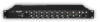
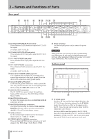
2 − Names and Functions of Parts Rear panel t ST 2/AUX OUTPUTS (XLR connectors) Theses balanced XLR connectors output the ST 2/AUX bus signal. (1: GND 2: HOT 3: COLD) y ST 2/AUX OUTPUTS (RCA pin jacks) These unbalanced RCA pin jacks output the ST 2/AUX bus signal. u ST 1 OUTPUTS (RCA pin jacks) These unbalanced RCA pin jacks output the ST1 bus signal. i ST 1 OUTPUTS (XLR connectors) Theses balanced XLR connectors output the ST 1 bus signal. (1: GND 2: HOT 3: COLD) o Signal ground (SIGNAL GND) connector Use a commercially available PVC-covered cord to connect this connector to the signal ground. Note that this is NOT an electrical safety ground (earth). p Ground lift (GND LIFT) switch Even when the ground connector is used to ground the unit, this ground connection can be interrupted (ground lift) by setting the GND LIFT switch to the left. a BUSS OUTPUT connectors The ST 2/AUX bus signal is output through these balanced TRS connectors. (Tip: HOT, Ring: COLD, Sleeve: GND) s MASTER BUSS IN switch Set where the signals input from the MASTER BUSS IN connectors are sent. d MASTER BUSS IN input connectors The signal input through the balanced TRS MASTER BUSS IN connectors can be set to be sent to the ST 1 (MAIN), ST 2/AUX or both busses at once. f LEVEL switches Set the nominal input/output levels for the channel inputs/outputs to +4 dBu or -10 dBV. g STEREO INPUTS (L/MONO) connectors These are balanced TRS line input connectors for each channel. (Tip: HOT, Ring: COLD, Sleeve: GND) h Power connector Use the included power cord to connect the power source. CAUTION When using this unit, always use the included power cord. Moreover, do not use the included power cord with any other equipment. Misuse of a power cord could cause malfunction, fire or electric shock. Bottom panel j j ST 2/AUX switch Set this to ST 2 to send the input signals directly to the ST 2/AUX buss after being adjusted by the ST 2/AUX knobs. Since this has no effect on the signals sent to the ST 1 buss, this unit can be used as mixer with two independent stereo busses. Set this to AUX to send the signals to the ST 2/AUX buss after being adjusted by the ST 1 and then the ST 2/ AUX knobs. Set this way, ST 1 can be used as the main buss and ST 2/AUX can be used as an AUX send. 6 TASCAM LM-8ST
-
 1
1 -
 2
2 -
 3
3 -
 4
4 -
 5
5 -
 6
6 -
 7
7 -
 8
8 -
 9
9 -
 10
10 -
 11
11 -
 12
12
 |
 |
