TP-Link TL-SG3109 User Guide - Page 65
Configuring the Spanning Tree Protocol
 |
UPC - 845973020484
View all TP-Link TL-SG3109 manuals
Add to My Manuals
Save this manual to your list of manuals |
Page 65 highlights
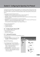
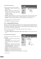
Section 9. Configuring the Spanning Tree Protocol The Spanning Tree Protocol (STP) provides tree topography for any arrangement of bridges. STP also provides a single path between end stations on a network, eliminating loops. Loops occur when alternate routes exist between hosts. Loops in an extended network can cause bridges to forward traffic indefinitely, resulting in increased traffic and reducing network efficiency. The TP-Link device supports the following STP versions: Classic STP - Provides a single path between end stations, avoiding and eliminating loops. For more information on configuring Classic STP, see Configuring the Classic STP. Rapid STP - Detects and uses network topologies that provide faster convergence of the spanning tree, without creating forwarding loops. For more information on configuring Rapid STP, see Configuring the Rapid STP. Multiple STP - Provides various load balancing scenarios. For example, if port A is blocked in one STP instance, the same port can be placed in the Forwarding State in another STP instance. For more information on configuring Multiple STP, see Configuring the Multiple STP. This section contains the following topics: Configuring the Classic STP Configuring the Rapid STP Configuring the Multiple STP 9.1 Configuring the Classic STP This section describes the following topics: Defining STP Properties Defining STP Interface Settings 9.1.1 Defining STP Properties The STP Properties Page contains parameters for enabling STP on the device. To define STP properties: 1. Click System > Bridging Info > Spanning Tree > STP > Properties. The STP Properties Page opens: Figure 84: STP Properties Page The STP Properties Page contains the following fields: Spanning Tree State - Indicates whether STP is enabled on the device. The possible field values are: - Enable - Enables STP on the device. - Disable - Disables STP on the device. STP Operation Mode - Specifies the STP mode that is enabled on the device. The possible field values are: - Classic STP - Enables Classic STP on the device. This is the default value. 58
-
 1
1 -
2
-
3
-
4
-
5
-
6
-
7
-
8
-
9
-
10
-
11
-
12
-
13
-
14
-
15
-
16
-
17
-
18
-
19
-
20
-
21
-
22
-
23
-
24
-
25
-
26
-
27
-
28
-
29
-
30
-
31
-
32
-
33
-
34
-
35
-
36
-
37
-
38
-
39
-
40
-
41
-
42
-
43
-
44
-
45
-
46
-
47
-
48
-
49
-
50
-
51
-
52
-
53
-
54
-
55
-
56
-
57
-
58
-
59
-
 60
60 -
 61
61 -
 62
62 -
 63
63 -
 64
64 -
 65
65 -
 66
66 -
 67
67 -
 68
68 -
 69
69 -
 70
70 -
71
-
72
-
73
-
74
-
75
-
76
-
77
-
78
-
79
-
80
-
81
-
82
-
83
-
84
-
85
-
86
-
87
-
88
-
89
-
90
-
91
-
92
-
93
-
94
-
95
-
96
-
97
-
98
-
99
-
100
-
101
-
102
-
103
-
104
-
105
-
106
-
107
-
108
-
109
-
110
-
111
-
112
-
113
-
114
-
115
-
116
-
117
-
118
-
119
-
120
 |
 |
