Toshiba 72HM196 Operating Guide - Page 9
TV back panel connections
 |
UPC - 022265251485
View all Toshiba 72HM196 manuals
Add to My Manuals
Save this manual to your list of manuals |
Page 9 highlights
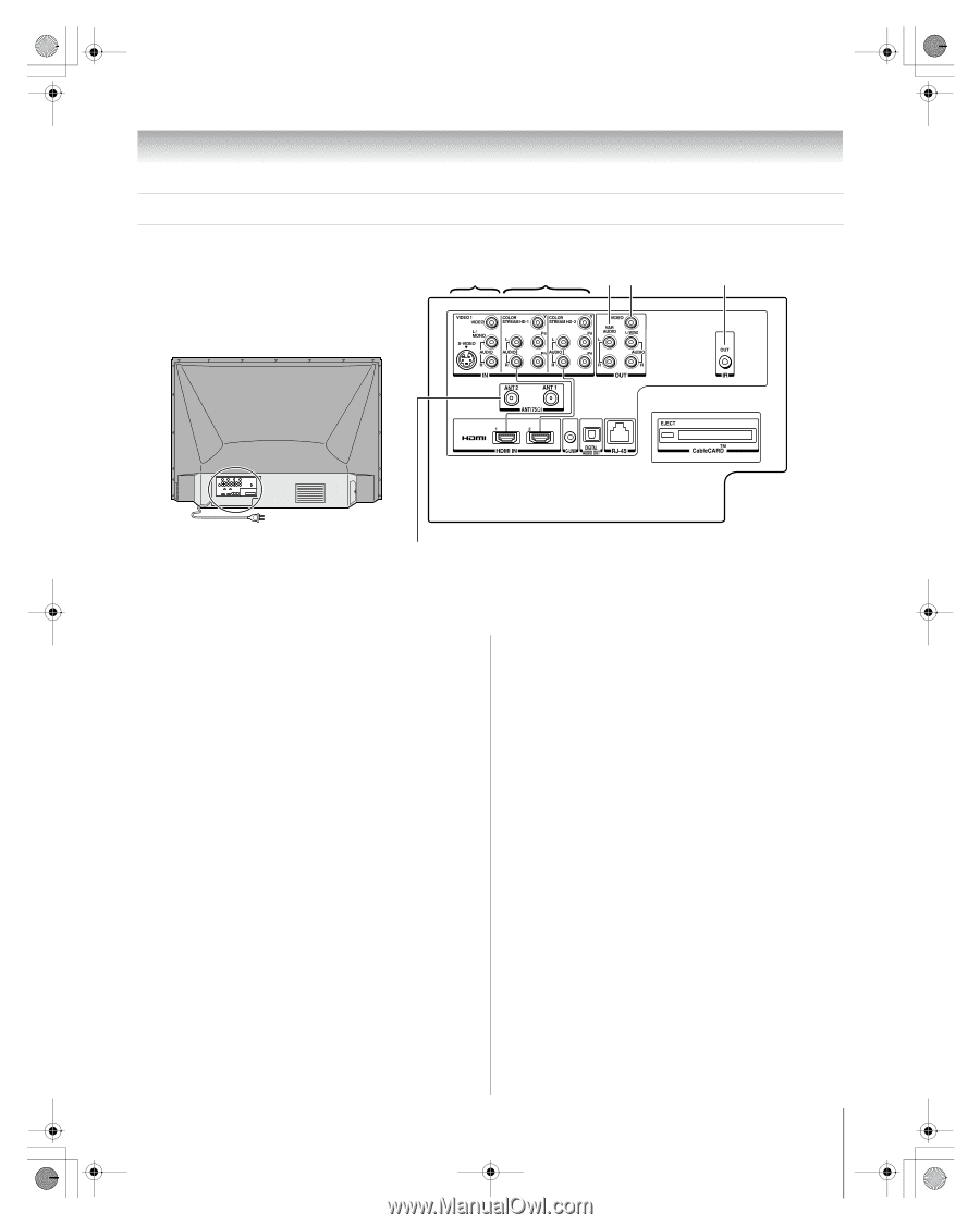
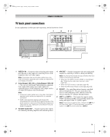
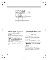
HM196_EN.book Page 9 Tuesday, May 30, 2006 2:18 PM Chapter 1: Introduction TV back panel connections For an explanation of cable types and connections, see the Installation Guide. 1 2 34 5 6 1 VIDEO 1 IN - Composite video and analog audio inputs plus optional S-video inputs for connecting devices with composite video or S-video output. Note: Composite video and S-video cables carry only video information; separate audio cables are required for a complete connection. 2 ColorStream® HD-1 IN and ColorStream® HD-2 IN - Two sets of ColorStream® high-definition component video inputs (with analog stereo audio inputs) for connecting devices with component video output, such as a Toshiba DVD player with ColorStream®. Note: • Component video cables carry only video information; separate audio cables are required for a complete connection. • HDMI 1 (and 2) share analog audio inputs with ColorStream HD-1 (and HD-2). To specify the use of the audio inputs for a connected ColorStream (component video) device, see "Setting the ColorStream HD audio mode" on page 28. 3 Variable Audio OUT - Standard analog audio outputs for connecting an analog amplifier with external speakers. 4 A/V OUT - Standard composite video and analog audio outputs for connecting a VCR for editing and dubbing. Note: The A/V OUT terminals will output AUDIO ONLY (no video) in the following instances: • When the TV's INPUT mode is HDMI, or ColorStream (- "Selecting the video input source to view," page 32). • When the POP window is open (- page 40). • When the MP3 Audio Player is active (- page 66). 5 IR OUT - For controlling infrared remote-controlled devices through the TV. You can connect up to two devices with an IR blaster cable, and then control the devices using the TV's IR pass-through features. 6 ANT 1 and ANT 2 - Two inputs that support analog (NTSC) and digital (ATSC) off-air antenna signals and analog and digital Cable TV (QAM) signals. Note: If you have an antenna only, connect it to ANT 1. If you have both cable TV and an antenna, connect the cable TV to ANT 1 and the antenna to ANT 2. 9 HM196 (E/F) Web 213:276
-
 1
1 -
2
-
3
-
 4
4 -
 5
5 -
 6
6 -
 7
7 -
 8
8 -
 9
9 -
 10
10 -
 11
11 -
 12
12 -
 13
13 -
 14
14 -
15
-
16
-
17
-
18
-
19
-
20
-
21
-
22
-
23
-
24
-
25
-
26
-
27
-
28
-
29
-
30
-
31
-
32
-
33
-
34
-
35
-
36
-
37
-
38
-
39
-
40
-
41
-
42
-
43
-
44
-
45
-
46
-
47
-
48
-
49
-
50
-
51
-
52
-
53
-
54
-
55
-
56
-
57
-
58
-
59
-
60
-
61
-
62
-
63
-
64
-
65
-
66
-
67
-
68
-
69
-
70
-
71
-
72
-
73
-
74
-
75
-
76
-
77
-
78
-
79
-
80
-
81
-
82
-
83
-
84
-
85
-
86
-
87
-
88
-
89
-
90
-
91
-
92
 |
 |