Toshiba SD-2700U Owners Manual - Page 12
Identification of Controls, Front panel, Rear panel
 |
View all Toshiba SD-2700U manuals
Add to My Manuals
Save this manual to your list of manuals |
Page 12 highlights
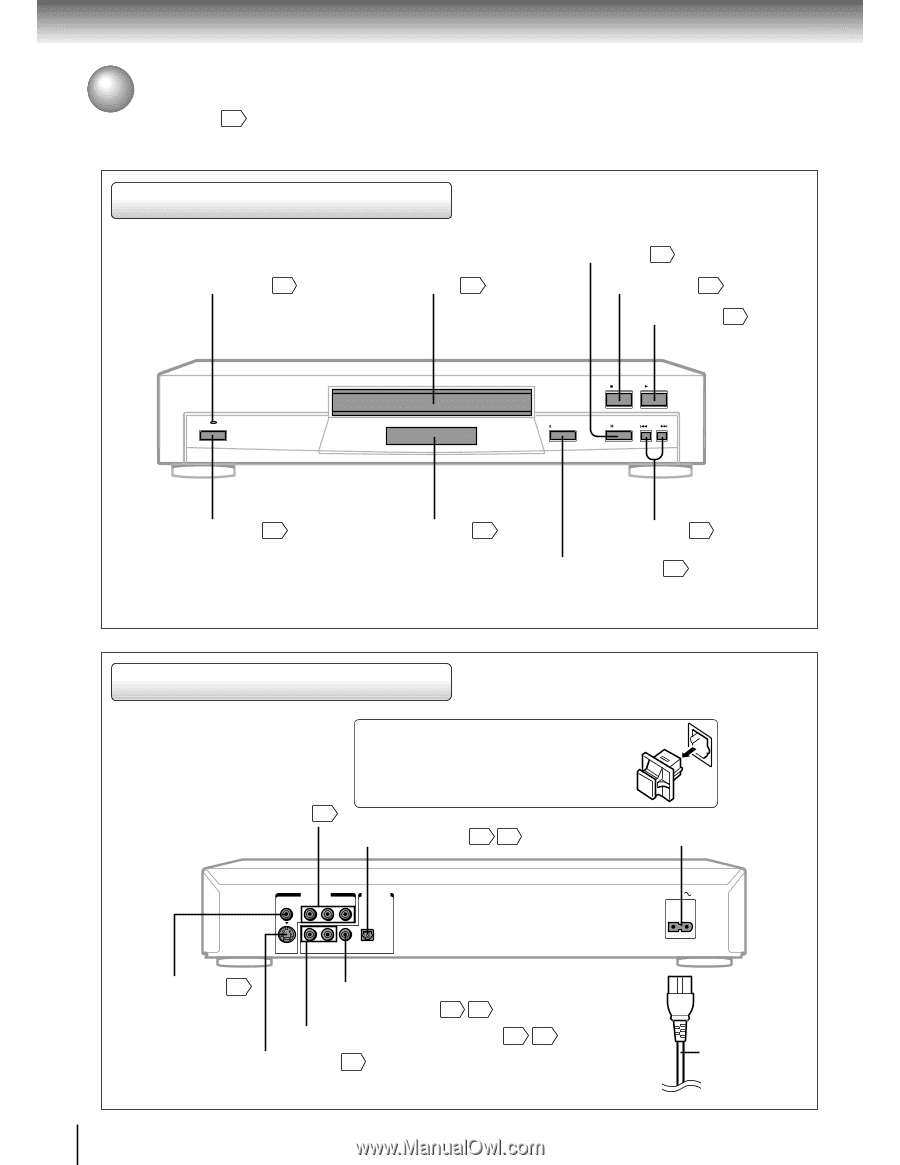
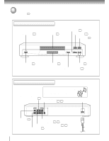
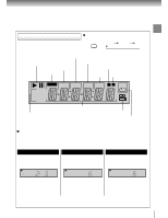
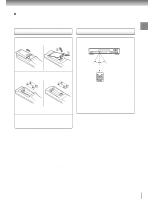
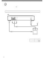
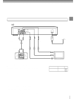
Introduction Identification of Controls See the page in for details. Front panel POWER indicator 20 Disc tray 20 POWER PAUSE button 21 STOP button 21 PLAY button 20 STOP PLAY OPEN/CLOSE PAUSE SKIP POWER button 20 DVD display 13 SKIP buttons 25 OPEN/CLOSE button 20 Rear panel VIDEO OUT (Y/PB/PR) (Component video) jacks 17 When connecting the optical digital cable, remove the cap and fit the connector into the jack firmly. When not using the jack, keep the cap inserted to protect it from dust intrusion. BITSTREAM/PCM OPTICAL AUDIO OUT jack 18 19 AC inlet VIDEO OUT VIDEO Y PB PR AUDIO OUT S R L COAXIAL OPTICAL ANALOG BITSTREAM/PCM VIDEO OUT jack 16 BITSTREAM/PCM COAXIAL AUDIO OUT jack 18 19 ANALOG AUDIO OUT (L/R) jacks 16 17 S VIDEO OUT jack 16 AC IN Power cord 12
-
 1
1 -
2
-
3
-
4
-
5
-
6
-
 7
7 -
 8
8 -
 9
9 -
 10
10 -
 11
11 -
 12
12 -
 13
13 -
 14
14 -
 15
15 -
 16
16 -
 17
17 -
18
-
19
-
20
-
21
-
22
-
23
-
24
-
25
-
26
-
27
-
28
-
29
-
30
-
31
-
32
-
33
-
34
-
35
-
36
-
37
-
38
-
39
-
40
-
41
-
42
-
43
-
44
-
45
-
46
-
47
-
48
-
49
-
50
-
51
 |
 |