Toshiba Satellite Pro 4600 Replacement Instructions
Toshiba Satellite Pro 4600 Manual
 |
View all Toshiba Satellite Pro 4600 manuals
Add to My Manuals
Save this manual to your list of manuals |
Toshiba Satellite Pro 4600 manual content summary:
- Toshiba Satellite Pro 4600 | Replacement Instructions - Page 1
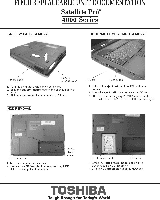
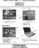
FIELD REPLACEABLE UNIT DOCUMENTATION Satellite Prom" 4600 Series BATTERY PACK REMOVAL OPTIONAL PCMCIA CARO REMOVAL Battery pack release lever 1 Turn the computer upside down as shown 2 Slide the battery release lever in the direction of the arrow 3 Slide the battery pack. the right and lift it - Toshiba Satellite Pro 4600 | Replacement Instructions - Page 2
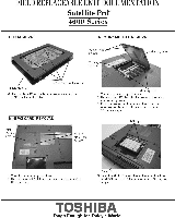
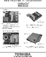
FIELD REPLACEABLE UNIT DOCUMENTATION Satellite PrO' 4600 Series HOD REMOVAL MEMORY MODULE REMOVAL 1.5x1blac SCreWS 0.- - H. bracket Flat head screws 5 RODemove four M.el Ike head screws securing the H bracket . the dTive MINI PCI CARD REMOVAL 5.4 a:' rts °" Memory clips 1 Tum the computer - Toshiba Satellite Pro 4600 | Replacement Instructions - Page 3
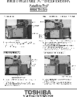
Satellite Prom" 4600 Series MODEM REMOVAL M2 br RJ11 Jack Modem slot cover lut25.4 black .1. I Remove one fil2.5w1 black screw securing ihe modem 2 n' le'ttl e ngt' ea[': te'h: 'tlaU tISgn a l°eFaTeVlhe o latches securing Me len sole of ihe modem Lad cover KEYBOARD REMOVAL odem 3. Remove - Toshiba Satellite Pro 4600 | Replacement Instructions - Page 4
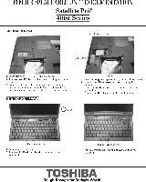
FIELD REPLACEABLE UNIT DOCUMENTATION Satellite Prom" 4600 Series KEYBOARD REMOVAL TOP COVER REMOVAL M2 Steblac Keyboard g: gl=rc=0V,%17=T system board and lift out me keyboard TOP COVER REMOVAL K, :,,ylbeoard M2 5,16 sb = Est' M2 5,6 black 1 Turn Me computer upside down and remove the VIL n. - Toshiba Satellite Pro 4600 | Replacement Instructions - Page 5
FIELD REPLACEABLE UNIT DOCUMENTATION Satellite Prom" 4600 Series FDD REMOVAL PJ63 M2.5. braes screw F. a ssy Iyisd.rn= MO cable from R.I63 on the 2. IMr6=1:2.5a6 brass screws securing the 3 Li out. FDD assembly. CO-ROMIOVO ROM DRIVE REMOVAL M2.50 black screw. ° 5 IPsccoanneect the F00 cable - Toshiba Satellite Pro 4600 | Replacement Instructions - Page 6
REPLACEABLE UNIT DOCUMENTATION Satellite Prom" 4600 Series RTC REMOVAL WIRELESS SWITCHILED BOARD REMOVAL PJ201 ' 69 RTC battery i :gtegn:Ilgr uCehle;ornP.1201eroYn h e 3 U=VC rdbettery out of the slot SPEAKERS REMOVAL Wireless .M.0 board Wireless switch/LED board cable 1. Remove Remove - Toshiba Satellite Pro 4600 | Replacement Instructions - Page 7
FIELD REPLACEABLE UNIT DOCUMENTATION Satellite Prom" 4600 Series BATTERY BOARD REMOVAL ANTENNA INTERFACE BOARD REMOVAL 1.12.5,5 bnee Pol.2.5.6 brass screws Plastic bra. Battery board 1. Remove two WI2.5x6 brass screws securing the plastic 2. bOwriEntcl m!Idle battery board cable from P.I810 on - Toshiba Satellite Pro 4600 | Replacement Instructions - Page 8
FIELD REPLACEABLE UNIT DOCUMENTATION Satellite Prci 4600 Series CPU BOARD REMOVAL • e LOCK OPEN ft ommy SYSTEM BOARD REMOVAL 2 Ville:it chi uulEki esrecriEge2OPPNPOVon 2:7 AR. rd bind 1 Remore..IRSN6 Mass sorewrs secumg the moot brace LM mi Me pl.. IN.emtl iM noo comol - Toshiba Satellite Pro 4600 | Replacement Instructions - Page 9
FIELD REPLACEABLE UNIT DOCUMENTATION Satellite Prom" 4600 Series IPSILED BOARD REMOVAL LED lens LED board M2x1 brass LEDISENSOR BOARD REMOVAL LoE.Drn'Zer LED sensci board LED board bracket IPS board 1 cable out or the top cover and on the LED/Sensor board TOSHIBA Tough Enough for Today's World - Toshiba Satellite Pro 4600 | Replacement Instructions - Page 10
FIELD REPLACEABLE UNIT DOCUMENTATION Satellite' 4600 Series 14.' DISPLAY MASK REMOVAL YL 0 - 0 ()Latch FL INVERTER AND 14" LCD REMOVAL LCD module Display I .. bras. al 1 Remove Iwo mask seals at the bottom corners of the display assembly 2 Remove Iwo M25. brass screws 3Thep ate 22 latch. - Toshiba Satellite Pro 4600 | Replacement Instructions - Page 11
FIELD REPLACEABLE UNIT DOCUMENTATION Satellite' 4600 Series 15" DISPLAY MASK REMOVAL e el es et I O.h FL INVERTER AND 15" LCD REMOVAL LCD module III seals ° Mask seals 1 Remove nvo mask seals at. bottom corners of the mmlay assembly Remove two M2.5. brass scream 3 There men secuung M-
-
 1
1 -
 2
2 -
 3
3 -
 4
4 -
 5
5 -
 6
6 -
 7
7 -
8
-
9
-
10
-
11
 |
 |

FIELD
REPLACEABLE
UNIT
DOCUMENTATION
Satellite
Prom"
4600
Series
BATTERY
PACK
REMOVAL
OPTIONAL
PCMCIA
CARO
REMOVAL
Battery
pack
release
lever
Pe
cars
1
Turn
the
computer
upside
down
as
shown
2
Slide
the
battery
release
lever
in
the
direction
of
the
arrow
3
Slide
the
battery
pack.
the
right
and
lift
it
out
HOD
REMOVAL
bl
H.
slot
cove
1
Turn
the
computer
upside
down
2
I
:IO
r
t
'
cO
vv
e
et7d
'
pTtt
b
t
'
h
a
e
ck
sa
1
Pullout
the
ejed
button
of
the
PC
card
to
be
room..
2
Press
Me
eject
button
and
remove
the
PC
card
NOTE
Before
rempong
any
PCMCIA
derrce
make
make
ors
-
STOPPED
-
rn
ine
PC
Card
Manager.
HOD
bracket
handle
H.
assy
3.
Grasp
the
HOD
bracket
handle
and
pull
to
disconnect
the
1100
assembly
d
then=
assembly
out
of
the
H.
bay
TOSHIBA
Tough
Enough for
Today's
World