Toshiba Tecra A8 PTA83C-KF801E Users Manual Canada; English - Page 166
Removing a memory module, start, Control Panel, Performance and Maintenance, System, System Properties
 |
View all Toshiba Tecra A8 PTA83C-KF801E manuals
Add to My Manuals
Save this manual to your list of manuals |
Page 166 highlights
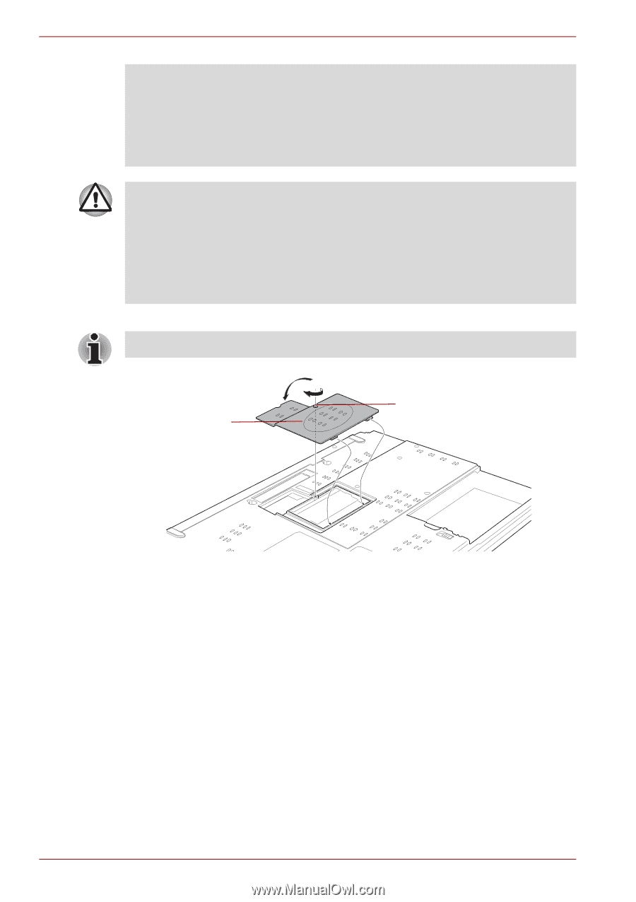
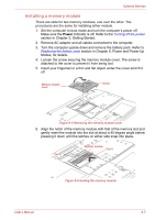
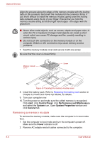
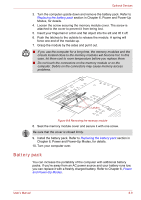
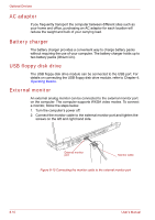
Optional Devices Align the grooves along the edges of the memory module with the locking tabs on the connector and insert the module into the connector firmly. If you find it difficult to install the memory module, gently prize the locking tabs outwards using the tip of your finger. Ensure that you hold the memory module along its left and right hand edges - the edges with the grooves in. ■ Never allow metal objects, such as screws, staples and paper clips, to enter the PC or keyboard. Foreign metal objects can create a short circuit, which can cause PC damage and fire, possibly resulting in serious injury. ■ Do not touch the connectors on the memory module or on the computer. Debris on the connectors may cause memory access problems. 7. Seat the memory module cover and secure it with one screw. Be sure that the cover is closed firmly. Memory module cover Screw Figure 8-7 Seating the memory module cover 8. Install the battery pack. Refer to Replacing the battery pack section in Chapter 6, Power and Power-Up Modes, for details. 9. Turn your computer over. 10. Turn the power on and make sure the added memory is recognized. Click start, click Control Panel, click Performance and Maintenance and select the System icon. Open System Properties window and click General tab. Removing a memory module To remove the memory module, make sure the computer is in boot mode then: 1. Set the computer to boot mode and turn the computer's power off. Make sure the Power indicator is off. 2. Remove AC adaptor and all cables connected to the computer. 8-8 User's Manual
-
 1
1 -
2
-
3
-
4
-
5
-
6
-
7
-
8
-
9
-
10
-
11
-
12
-
13
-
14
-
15
-
16
-
17
-
18
-
19
-
20
-
21
-
22
-
23
-
24
-
25
-
26
-
27
-
28
-
29
-
30
-
31
-
32
-
33
-
34
-
35
-
36
-
37
-
38
-
39
-
40
-
41
-
42
-
43
-
44
-
45
-
46
-
47
-
48
-
49
-
50
-
51
-
52
-
53
-
54
-
55
-
56
-
57
-
58
-
59
-
60
-
61
-
62
-
63
-
64
-
65
-
66
-
67
-
68
-
69
-
70
-
71
-
72
-
73
-
74
-
75
-
76
-
77
-
78
-
79
-
80
-
81
-
82
-
83
-
84
-
85
-
86
-
87
-
88
-
89
-
90
-
91
-
92
-
93
-
94
-
95
-
96
-
97
-
98
-
99
-
100
-
101
-
102
-
103
-
104
-
105
-
106
-
107
-
108
-
109
-
110
-
111
-
112
-
113
-
114
-
115
-
116
-
117
-
118
-
119
-
120
-
121
-
122
-
123
-
124
-
125
-
126
-
127
-
128
-
129
-
130
-
131
-
132
-
133
-
134
-
135
-
136
-
137
-
138
-
139
-
140
-
141
-
142
-
143
-
144
-
145
-
146
-
147
-
148
-
149
-
150
-
151
-
152
-
153
-
154
-
155
-
156
-
157
-
158
-
159
-
160
-
 161
161 -
 162
162 -
 163
163 -
 164
164 -
 165
165 -
 166
166 -
 167
167 -
 168
168 -
 169
169 -
 170
170 -
 171
171 -
172
-
173
-
174
-
175
-
176
-
177
-
178
-
179
-
180
-
181
-
182
-
183
-
184
-
185
-
186
-
187
-
188
-
189
-
190
-
191
-
192
-
193
-
194
-
195
-
196
-
197
-
198
-
199
-
200
-
201
-
202
-
203
-
204
-
205
-
206
-
207
-
208
-
209
-
210
-
211
-
212
-
213
-
214
-
215
-
216
-
217
-
218
-
219
-
220
-
221
-
222
-
223
-
224
-
225
-
226
-
227
-
228
-
229
-
230
-
231
-
232
-
233
-
234
-
235
-
236
-
237
-
238
-
239
-
240
-
241
-
242
-
243
-
244
-
245
-
246
-
247
-
248
-
249
-
250
-
251
-
252
-
253
-
254
-
255
-
256
-
257
-
258
-
259
-
260
-
261
-
262
-
263
-
264
-
265
-
266
-
267
-
268
-
269
-
270
-
271
-
272
-
273
-
274
-
275
-
276
 |
 |