Troy-Bilt TB225 Operation Manual - Page 6
Assembly Instructions - throttle cable
 |
View all Troy-Bilt TB225 manuals
Add to My Manuals
Save this manual to your list of manuals |
Page 6 highlights
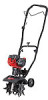
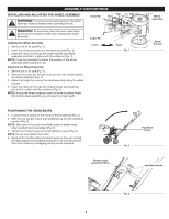
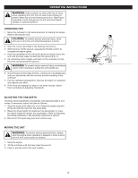
ASSEMBLY INSTRUCTIONS INSTALLING AND ADJUSTING THE WHEEL ASSEMBLY WARNING: To prevent serious personal injury, the wheel assembly must be installed when operating the unit. Clevis Pin WARNING: To avoid injury from the tines, wear heavy gloves and a long sleeve shirt when installing the wheel assembly. Installing the Wheel Assembly 1. Set the unit on its side (Fig. 1). 2. Insert the wheel assembly into the wheel bracket (Fig. 1). 3. Insert the clevis pin through the wheel bracket and wheel assembly and lock it in place with the cotter pin (Fig. 1). NOTE: It may be necessary to adjust the position of the wheel assembly before using the unit. Adjusting the Wheel Assembly 1. Set the unit on its side (Fig. 1). 2. Remove the cotter pin and the clevis pin from the wheel bracket and wheel assembly (Fig. 1). 3. Adjust the height by moving the wheel assembly along the wheel bracket. 4. Insert the clevis pin through the wheel bracket and assembly and lock it in place with the cotter pin (Fig. 1). NOTE: Moving the wheel assembly down will raise the wheel height. Moving the wheel assembly up will lower the wheel height. Cotter Pin Lower Raise Fig. 1 Wheel Assembly Wheel Bracket POSITIONING THE HANDLEBARS 1. Loosen the two knobs on the inside of the handlebars (Fig. 3). 2. With the unit upright, swing the handlebars up into the operating position (Fig. 2). NOTE: Take care not to pinch the throttle cable or switch wires when positioning the handlebar (Fig. 3). 3. Tighten the knobs to secure the handlebars in place (Fig. 3). NOTE: Do not over tighten the knobs. 4. Readjust the throttle cable and switch wires so they are smooth and tight against the handlebar assembly. This will help prevent them from catching or snagging during normal operation. Handlebar Knobs Fig. 2 Throttle Cable and Switch Wires Handlebar Knobs Fig. 3 6
-
 1
1 -
 2
2 -
 3
3 -
 4
4 -
 5
5 -
 6
6 -
 7
7 -
 8
8 -
 9
9 -
 10
10 -
 11
11 -
 12
12 -
13
-
14
-
15
-
16
-
17
-
18
-
19
-
20
-
21
-
22
-
23
-
24
-
25
-
26
-
27
-
28
-
29
-
30
-
31
-
32
 |
 |
