Via EPIA-M10000G User Manual - Page 26
Case Connector, F_PANEL, Power Switch PW_BN, Reset Switch RESET, Power LED PWR LED, HDD LED, Speaker
 |
View all Via EPIA-M10000G manuals
Add to My Manuals
Save this manual to your list of manuals |
Page 26 highlights
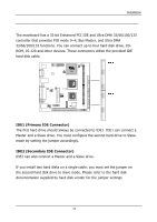
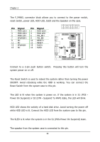
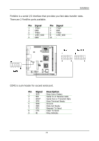
Chapter 2 Case Connector: F_PANEL The F_PANEL connector block allows you to connect to the power switch, reset switch, power LED, HDD LED, SLED and the Speaker on the case. 2 16 Pin Signal 1 PWR LED+ 3 PWR LED+ 5 PWR LED- 7 SPEAKER+ 9 NC 11 NC 13 SPEAKER- 15 NC Pin Signal 2 HDD LED+ 4 HDD LED- 6 PW_BN+ 8 PW_BN- 10 RESET+ 12 RESET- 14 SLED+ 16 SLED- 1 15 Power Switch (PW_BN) Connect to a 2-pin push button switch. system power on or off. Pressing this button will turn the Reset Switch (RESET) The Reset Switch is used to reboot the system rather than turning the power ON/OFF. Avoid rebooting while the HDD is working. You can connect the Reset Switch from the system case to this pin. Power LED (PWR LED) The LED is lit when the system is power on. If the system is in S1 (POS Power On Suspend) or S3 (STR - Suspend To RAM) state, the LED will blink. HDD LED HDD LED shows the activity of a hard disk drive. Avoid turning the power off while HDD LED is lit. Connect the HDD LED from the system case to this pin. SLED The SLED is lit when the system is in the S1 (POS-Power On Suspend) state. Speaker The speaker from the system case is connected to this pin. 18
-
 1
1 -
2
-
3
-
4
-
5
-
6
-
7
-
8
-
9
-
10
-
11
-
12
-
13
-
14
-
15
-
16
-
17
-
18
-
19
-
20
-
 21
21 -
 22
22 -
 23
23 -
 24
24 -
 25
25 -
 26
26 -
 27
27 -
 28
28 -
 29
29 -
 30
30 -
 31
31 -
32
-
33
-
34
-
35
-
36
-
37
-
38
-
39
-
40
-
41
-
42
-
43
-
44
-
45
-
46
-
47
-
48
-
49
-
50
-
51
-
52
-
53
-
54
-
55
-
56
-
57
-
58
-
59
-
60
-
61
-
62
-
63
-
64
-
65
-
66
-
67
-
68
-
69
-
70
-
71
-
72
-
73
-
74
-
75
-
76
-
77
-
78
-
79
-
80
 |
 |
