Via EPIA-PX10000G User Manual
Via EPIA-PX10000G - VIA Motherboard - Pico ITX Manual
 |
UPC - 825529001969
View all Via EPIA-PX10000G manuals
Add to My Manuals
Save this manual to your list of manuals |
Via EPIA-PX10000G manual content summary:
- Via EPIA-PX10000G | User Manual - Page 1
User's Manual EPIA-PX Version 1.11 August 16, 2007 - Via EPIA-PX10000G | User Manual - Page 2
, manual or otherwise without the prior written permission of VIA Technologies, Incorporated. Trademarks All trademarks are the property of their respective holders. PS/2 is a registered trademark of IBM Corporation. Award BIOS is a registered trademark of Phoenix Technologies - Via EPIA-PX10000G | User Manual - Page 3
. This equipment generates, uses and can radiate radio frequency energy and, if not installed and used in accordance with the instruction manual, may cause harmful interference to radio communications. Operation of this equipment in a residential area is likely to cause harmful interference - Via EPIA-PX10000G | User Manual - Page 4
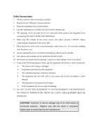
1. Always read the safety instructions carefully. 2. Keep this User's Manual for future reference. 3. Keep this equipment If any of the following situations arises, get the equipment checked by a service personnel: • The power cord or plug is damaged • Liquid has penetrated into the equipment • - Via EPIA-PX10000G | User Manual - Page 5
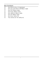
BOX CONTENTS One EPIA PX Pico-ITX Mainboard One ATA-133/100/66 IDE Ribbon Cable One PS/2 Ribbon Cable One Power Ribbon Cable One COM Port Ribbon Cable One DVI Ribbon Cable One Driver Utility CD Two Screws (for the COM port) i - Via EPIA-PX10000G | User Manual - Page 6
7 CONNECTING THE POWER SUPPLY 8 Pico-ITX 12-Pin Power Connector 8 BACK PANEL PORTS 9 VGA Port 9 RJ45 LAN Port 9 CONNECTORS 10 IDE Connector: IDE 10 Serial ATA Connectors: SATA 11 USB Pin Connector: USB 11 KBMS Connector: PS/2 11 Case Connector: Front Panel 12 Power Switch (PW_BN 12 - Via EPIA-PX10000G | User Manual - Page 7
25 Exit Without Saving 25 STANDARD CMOS FEATURES 26 Date 26 Time 26 Halt On 26 Video 26 IDE DRIVES 27 ADVANCED BIOS FEATURES 28 Virus Warning 28 Quick Power On Self-Test 28 First/Second/Third Boot Device 29 Boot Other Device 29 Boot Up NumLock Status 29 Typematic Rate Setting - Via EPIA-PX10000G | User Manual - Page 8
31 TM2 Bus VID 32 C7 CMPXCHGB 32 C7 NoExecute (NX 32 HARD DISK BOOT PRIORITY 33 ADVANCED CHIPSET FEATURES 34 Memory Hole 34 System BIOS Cacheable 34 Video RAM Cacheable INTEGRATED PERIPHERALS 39 Onboard Serial Port 39 VIA ONCHIP PCI DEVICE 40 Azalia HAD Controller 40 LAN Boot ROM 40 iv - Via EPIA-PX10000G | User Manual - Page 9
Auto restart 44 WAKEUP EVENT DETECT 45 PS2KB Wakeup Select 45 PS2KB Wakeup Key Select 45 PS2MS Wakeup Key Select 45 PS2 Keyboard Power On 46 PS2 Mouse Power On 46 PowerOn by PCI Card 46 Modem Ring Resume 46 RTC Alarm Resume 46 Date (of Month 46 Resume Time (hh:mm - Via EPIA-PX10000G | User Manual - Page 10
Maximum ASPM supported 48 Maximum Payload Size 48 FREQUENCY / VOLTAGE CONTROL 49 DRAM Clock 49 SET SUPERVISOR / USER PASSWORD 54 SAVE & EXIT SETUP 56 EXIT WITHOUT SAVING 57 DRIVER INSTALLATION 59 DRIVER UTILITIES 60 Getting Started 60 Running the Driver Utilities CD 61 CD CONTENT 62 vi - Via EPIA-PX10000G | User Manual - Page 11
This page is intentionally left blank. vii - Via EPIA-PX10000G | User Manual - Page 12
- Via EPIA-PX10000G | User Manual - Page 13
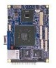
1 Specifications The ultra-compact and highly integrated VIA EPIA-PX Pico-ITX mainboard is the smallest form-factor available today. Through a high level of integration, the Pico-ITX measures at only 25% of the size of a Mini-ITX mainboard. The mainboard enables the creation of an exciting new - Via EPIA-PX10000G | User Manual - Page 14
Chapter 1 MAINBOARD SPECIFICATIONS CPU • Supports VIA C7 1.0GHz NanoBGA2 Processor Chipset • VIA VX700 Advanced All-in-One System Processor Memory • pin connector) Serial ATA • 1 x SATA connector LAN • VIA VT6106S 10/100 Mbps Fast Ethernet Controller with Power Management Functions Audio • VIA - Via EPIA-PX10000G | User Manual - Page 15
Output • 1 Multimedia connector to support External TV-Out Interface, Video Capture Port Interface and Low Pin Count Interface. (One VT1625M add-on card is required.) • 1 x Pico-ITX power connector BIOS • Award BIOS with LPC 4/8Mbit flash memory capacity Form Factor • Pico-ITX (10 layers) • 10 cm - Via EPIA-PX10000G | User Manual - Page 16
Chapter 1 MAINBOARD LAYOUT BACK PANEL LAYOUT 4 - Via EPIA-PX10000G | User Manual - Page 17
CHAPTER 2 Installation This chapter provides you with information about hardware installation procedures. It is recommended to use a grounded wrist strap before handling computer components. Electrostatic discharge (ESD) can damage some components. 5 - Via EPIA-PX10000G | User Manual - Page 18
Chapter 2 CPU The VIA EPIA-PX Pico-ITX mainboard can support VIA C7 NanoBGA2 processor. The processor requires a heatsink with fan for 1.0GHz SKU. CPU Fan: CPU_FAN The CPU_FAN runs on +5V. The black wire is Ground and should always be connected to GND. Pin Signal 1 1 FAN OUT 2 +5V 3 GND 6 - Via EPIA-PX10000G | User Manual - Page 19
Installation Memory Slot: DDR2_SODIMM The VIA EPIA-PX Pico-ITX mainboard provides one SODIMM slot for DDR2 533 SDRAM memory modules and supports memory sizes up to 1GB. Insert the SODIMM module at a 45 degree angle. Push the SODIMM module back towards the board until the clips lock the module - Via EPIA-PX10000G | User Manual - Page 20
CONNECTING THE POWER SUPPLY The VIA EPIA-PX Pico-ITX mainboard supports a Pico-ITX power supply for the power system. Before inserting the power supply connector, always make sure that all components are installed correctly to ensure that no damage will be caused. Pico-ITX 12-Pin Power Connector To - Via EPIA-PX10000G | User Manual - Page 21
BACK PANEL PORTS The back panel has the following layout: Installation VGA Port The 15-pin female VGA connector can be used to connect to any analog VGA monitor. RJ45 LAN Port The mainboard provides a standard RJ45 port for enabling connections to networks. 9 - Via EPIA-PX10000G | User Manual - Page 22
connected to a single cable, the jumper on the second drive must be set to slave mode. Refer to the drive documentation supplied by the vendor for the jumper settings. Pin Signal 1 #IDERST 3 PDD7 5 PDD6 7 PDD5 9 PDD4 11 PDD3 13 PDD2 15 PDD1 17 PDD0 19 GND 21 PDDREQ 23 #PDIOW - Via EPIA-PX10000G | User Manual - Page 23
+USB_VD1 15 GND Pin Signal 2 NC 4 GND 6 +USB_VD3 8 -USB_VD3 10 +5V 12 -USB_VD0 14 +USB_VD0 16 GND 1 2 15 16 KBMS Connector: PS/2 The mainboard provides a PS2 pin header to attach a PS2 keyboard and mouse. Pin Signal 1 A5V 3 KBCLK 5 MSCLK Pin Signal 2 GND 4 KBDATA - Via EPIA-PX10000G | User Manual - Page 24
Connector: Front Panel This pin header allows you to connect the power switch, reset switch, power LED, HDD LED and the case speaker. Pin Signal 1 PW_LED 3 PW_LED 5 SUS_LED 7 +5V 9 GND 11 #EXTSMI 13 SPEAK 15 NC Pin Signal 2 +5V 4 HDD_LED 6 PW_BN 8 GND 10 RST_SW 12 GND - Via EPIA-PX10000G | User Manual - Page 25
GND Installation 1 2 17 18 Serial Port Connector: COM Port COM port pin header can be used to attach additional ports for serial mouse or other serial devices. Pin Signal 1 #DCDA 2 RXDA 3 TXDA 4 #DTRA 5 GND Pin Signal 6 #DSRA 7 #RTSA 8 #CTSA 9 #RIA 10 NC 6 1 9 5 13 - Via EPIA-PX10000G | User Manual - Page 26
Connector: LVDS Panel The LVDS/DVI Panel connector allows you to connect the panel's LVDS cable directly to support LVDS panel without any need of a daughter card. Pin Signal 1 +12V 3 +12V 5 -LCD1_D2 7 +LCD1_D2 9 +12V 11 -LCD2_CLK 13 +LCD2_CLK 15 +5V 17 -LCD2_D3 19 +LCD2_D3 21 +5V - Via EPIA-PX10000G | User Manual - Page 27
-LCD2_D0 +LCD2_D1 -LCD2_D1 This connector work also as an interface and allows you to connect the EPIA PX's daughter card, PX-O. For LCD Inverter Control Signal Pin PX-O (CN10) Signal Pin CN5 Signal 6 SPD1 32 SPD1 7 SPCLK1 34 SPCLK1 8 ENAVDD2 37 ENAVDD2 9 ENABLT2 36 ENABLT2 15 - Via EPIA-PX10000G | User Manual - Page 28
Connector It is to connect to a multimedia daughter board for more multimedia functions. Pin Signal 1 HTVD2 3 +5V 5 +5V 7 HTVD12 67 GPIO3 69 #SIOSMI 71 #LDRQ1 73 LAD1 75 SERIRQ 77 GND 79 SIOOSC2 Pin Signal 2 HTVD8 4 HTVD7 6 HTVD10 8 +5V 10 HTVD6 12 HTVD4 14 HTVCLKR - Via EPIA-PX10000G | User Manual - Page 29
will explain how to change the settings of the mainboard functions using the jumpers. Clear CMOS: CMOS Reset The onboard CMOS RAM stores system configuration data and has an onboard battery power supply. To reset the CMOS settings, set the jumper on pins 2 and 3 while the system is off. Return the - Via EPIA-PX10000G | User Manual - Page 30
- Via EPIA-PX10000G | User Manual - Page 31
CHAPTER 3 BIOS Setup This chapter gives a detailed explanation of the BIOS setup functions. 19 - Via EPIA-PX10000G | User Manual - Page 32
Chapter 3 ENTERING SETUP Power on the computer and press during the beginning of the boot sequence to enter the BIOS setup menu. If you missed the BIOS setup entry point, you may restart the system and try again. 20 - Via EPIA-PX10000G | User Manual - Page 33
CONTROL KEYS Keys Up Arrow Down Arrow Left Arrow Right Arrow Enter Escape Page Up / + Page Down / F1 F5 F6 F7 F9 F10 BIOS Setup Description Move to the previous item Move to the next item Move to the item in the left side Move to the item in - Via EPIA-PX10000G | User Manual - Page 34
The main menu displays all the BIOS setup categories. Use the Up/Down/ Left/Right arrow keys to select any item or sub-menu. Description of the selected/highlighted category is displayed - Via EPIA-PX10000G | User Manual - Page 35
BIOS Setup GETTING HELP The BIOS setup program provides a "General Help" screen. You can display this screen from any menu/sub-menu by pressing . The help screen displays the keys for using and navigating the BIOS setup. Press to exit the help screen. 23 - Via EPIA-PX10000G | User Manual - Page 36
Chapter 3 MAIN MENU Phoenix - AwardBIOS CMOS Setup Utility Standard CMOS Features Advanced BIOS Features Advanced Chipset Features Integrated Peripherals Power Management Setup PnP / PCI Configurations Frequency / Voltage Control Load Fail-Safe Defaults Load Optimized Defaults Set Supervisor - Via EPIA-PX10000G | User Manual - Page 37
for minimal and stable system operations. Load Optimized Defaults Use this menu option to load BIOS default settings for optimal and high performance system operations. Set Supervisor Password Use this menu option to set the BIOS supervisor password. Set User Password Use this menu option to set the - Via EPIA-PX10000G | User Manual - Page 38
Chapter 3 STANDARD CMOS FEATURES Date (mm:dd:yy) Time (hh:mm:ss) IDE Channel 0 Master IDE Channel 0 Slave IDE Channel 1 Master IDE Channel 1 Slave Phoenix - AwardBIOS CMOS Setup Utility Standard CMOS Features Tue, Jul 13 1999 11 : 20 : 55 Item Help Menu Level Change the day, month, year and - Via EPIA-PX10000G | User Manual - Page 39
IDE DRIVES BIOS Setup IDE HDD Auto-Detection Phoenix - AwardBIOS CMOS Setup Utility IDE Channel 0 you enter incorrect information in this category. Select "Auto" whenever possible. If you select "Manual", make sure the information is from your hard disk vendor or system manufacturer. Below is a - Via EPIA-PX10000G | User Manual - Page 40
Phoenix - AwardBIOS CMOS Setup Utility Advanced BIOS Features CPU Feature Hard Disk Boot Priority Virus Warning Quick Power On Self Test First Boot Device Second Boot Device Third Boot Device Boot Other Device Boot Up NumLock Status Typematic Rate Setting Typematic Rate (Chars/ - Via EPIA-PX10000G | User Manual - Page 41
Second/Third Boot Device Set the boot device sequence as BIOS attempts to load the disk operating system. Setting LS120 boot device allowed Boot Up NumLock Status Set the NumLock status when the system is powered on. Setting On Off Description Forces keypad to behave as 10-key Forces keypad to - Via EPIA-PX10000G | User Manual - Page 42
. Setting Setup System Description Password prompt appears only when end users try to run BIOS Setup Password prompt appears every time when the computer is powered on and when end users try to run BIOS Setup MPS Variation Control for OS Settings: [1.1, 1.4] OS Select For DRAM > 64MB Select OS2 - Via EPIA-PX10000G | User Manual - Page 43
to Thermal Thermal Management TM2 Bus Ratio TM2 Bus VID C7 CMPXCHGB C7 NoExecute (NX) Phoenix - AwardBIOS CMOS Setup Utility CPU Feature [16 Min] [Thermal Monitor 1] [ 0 X] [0.700V] [Enabled] [Disabled] Item Help Menu Level BIOS Setup : Move Enter: Select F5: Previous Values +/-/PU/PD: Value - Via EPIA-PX10000G | User Manual - Page 44
, 1.324V, 1.340V, 1.356V, 1.372V, 1.388V, 1.404V, 1.420V, 1.436V, 1.452V, 1.468V, 1.484V, 1.500V, 1.516V, 1.532V, 1.548V, 1.564V, 1.580V, 1.596V, 1.612V, 1.628V, 1.644V, 1.660V, 1.676V, 1.692V, 1.708] C7 CMPXCHGB Settings: [Enabled, Disabled] C7 NoExecute (NX) Settings: [Enabled, Disabled] 32 - Via EPIA-PX10000G | User Manual - Page 45
HARD DISK BOOT PRIORITY BIOS Setup Phoenix - AwardBIOS CMOS Setup Utility Hard Disk Boot Priority 1. Pri. Master : 2. Pri. Slave : 3. Sec. Master : 4. Sec. Slave : 5. USBHDD0 : 6. USBHDD1 : 7. USBHDD2 : 8. Bootable Add-In Cards - Via EPIA-PX10000G | User Manual - Page 46
CHIPSET FEATURES Phoenix - AwardBIOS CMOS Setup Utility Advanced Chipset Features AGP & P2P Bridge Control CPU & PCI Bus Control Memory Hole System BIOS Cacheable Video RAM Cacheable Init Display First [Press Enter] [Press Enter] [Disabled] [Enabled] [Disabled] [PCI Slot] Item Help Menu Level - Via EPIA-PX10000G | User Manual - Page 47
BIOS Setup Select Display Device This setting refers to the type of display being used with the system. Settings: [CRT, LCD, CRT+LCD, TV, LCD+TV] Panel Type This setting refers to the native resolution of the display being used with the system. Key in a HEX number. Settings: [Min = 0000, - Via EPIA-PX10000G | User Manual - Page 48
cycles that hit the aperture range are forwarded to the AGP without any translation. Settings: [32MB, 64MB, 128MB, 256MB, 512MB, 1G] AGP 2.0 Mode This mainboard supports the AGP 4x interface. When the AGP 4x video card is used, it can transfer video data at 1066MB/s. AGP 4x is backward compatible - Via EPIA-PX10000G | User Manual - Page 49
BIOS Setup AGP Driving Control This item is used to signal driving current on AGP cards to auto or manual. Settings: [Auto, Manual] AGP Fast Write This item is used to enable or disable the caching of display data for the video memory of the processor. Settings: [Enabled, Disabled] AGP Master 1 WS - Via EPIA-PX10000G | User Manual - Page 50
Chapter 3 CPU & PCI BUS CONTROL PCI Master 0 WS Write PCI Delay Transaction DRDY_Timing Phoenix - AwardBIOS CMOS Setup Utility CPU & PCI Bus Control [Enabled] [Enabled] [Optimize] Item Help Menu Level : Move Enter: Select F5: Previous Values +/-/PU/PD: Value F10: Save F6: Fail-Safe Defaults - Via EPIA-PX10000G | User Manual - Page 51
INTEGRATED PERIPHERALS VIA OnChip PCI Device Onboard Serial Port USB Device Setting Phoenix - AwardBIOS CMOS Setup Utility Integrated Peripherals [Press Enter] [3F8 / IRQ4] [Press Enter] Item Help Menu Level BIOS Setup : Move Enter: Select F5: Previous Values +/-/PU/PD: Value F10: Save F6: - Via EPIA-PX10000G | User Manual - Page 52
ONCHIP PCI DEVICE Azalia HDA Controller LAN Boot ROM Phoenix - AwardBIOS CMOS Setup Utility VIA OnChip PCI Device [Auto] [Enabled] Item Help Menu Level : Move Enter: Select F5: Previous Values +/-/PU/PD: Value F10: Save F6: Fail-Safe Defaults ESC: - Via EPIA-PX10000G | User Manual - Page 53
USB DEVICE SETTING BIOS Setup Phoenix - AwardBIOS CMOS Setup Utility USB Device Setting USB 1.0 Controller USB 2.0 Controller USB Operation Mode USB Keyboard Function USB Storage Function [Enabled] [Enabled] [High - Via EPIA-PX10000G | User Manual - Page 54
of USB Keyboard Settings: [Enabled, Disabled] USB Storage Function Enable or disable Legacy support of USB Mass Storage Settings: [Enabled, Disabled] No Device Setting Auto mode FDD mode HDD mode Description According to contents of USB MSD decide boot - Via EPIA-PX10000G | User Manual - Page 55
Blank] [3] [Instant-Off] [Auto] [Off] [Press Enter] Item Help Menu Level BIOS Setup : Move Enter: Select F5: Previous Values +/-/PU/PD: Value F10: Save F6 contexts. S3/Suspend To RAM (STR) is a power-down state. In this state, power is supplied only to essential components such as main memory and - Via EPIA-PX10000G | User Manual - Page 56
Off Description System is turned off if power button is pressed for more than four seconds Power button functions as a normal power-on/-off button Run VGABIOS if S3 Resume Select whether to run VGA BIOS if resuming from S3 state. necessary for older VGA drivers. This is only Settings: [Auto, Yes - Via EPIA-PX10000G | User Manual - Page 57
EVENT DETECT BIOS Setup PS2KB Wakeup Select PS2KB Wakeup Key Select PS2MS Wakeup Key Select PS2 Keyboard Power On PS2 Mouse Power On PowerOn Password] PS2KB Wakeup Key Select Sets a Hot Key to restore the system from the power saving mode to an active state. Settings: [Ctrl+F1, Ctrl+F2, Ctrl+F3, - Via EPIA-PX10000G | User Manual - Page 58
ports, etc. Settings: [By OS, Enabled] Modem Ring Resume Settings: [By OS, Enabled] RTC Alarm Resume Sets a scheduled time and/or date to automatically power on the system. Settings: [Disabled, Enabled] Date (of Month) The field specifies the date for "RTC Alarm Resume". Resume Time (hh:mm:ss) The - Via EPIA-PX10000G | User Manual - Page 59
Disabled] [Enabled] [Enabled] ** PCI Express relative items ** Maximum ASPM supported Maximum Payload Size [L0s&L1] [4096] Item Help Menu Level Select Yes you are an experienced user. PNP OS Installed Setting Yes No Description BIOS will only initialize the PnP cards used for booting (VGA, IDE, - Via EPIA-PX10000G | User Manual - Page 60
Description BIOS will automatically assign IRQ, DMA and memory base address fields Unlocks "IRQ Resources" for manual configuration PCI/VGA Palette Snoop Settings: [Disabled, Enabled] Assign IRQ For VGA/USB Assign IRQ for VGA and USB devices. Settings: [Disabled, Enabled] Maximum ASPM supported - Via EPIA-PX10000G | User Manual - Page 61
[Enabled] [Disabled] Item Help Menu Level BIOS Setup : Move Enter: Select F5: Previous Help F7: Optimized Defaults DRAM Clock The chipset supports synchronous and asynchronous mode between host clock and DRAM , Enabled] Spread Spectrum When the mainboard's clock generator pulses, the extreme - Via EPIA-PX10000G | User Manual - Page 62
F6: Fail-Safe Defaults ESC: Exit F1: General Help F7: Optimized Defaults DRAM Clock The chipset supports synchronous and asynchronous mode between host clock and DRAM clock frequency. Settings: [By SPD, 100 MHz performance rating than the original modules. Settings: [Manual, Auto By SPD] 50 - Via EPIA-PX10000G | User Manual - Page 63
Read to Precharge (Trtp) Settings: [2T, 3T] Write to Read CMD (Trtp) Settings: [1T/2T, 2T/3T] Write Recovery Time (Twr) Settings: [2T, 3T, 4T, 5T] DRAM Command Rate Settings: [2T Command, 1T Command] RDSAIT mode Settings: [Manual, Auto] BIOS Setup 51 - Via EPIA-PX10000G | User Manual - Page 64
Standard CMOS Features Advanced BIOS Features Advanced Chipset Features Integrated Peripherals Power Management Setup PnP BIOS F10 : Save & Exit Setup : Select Item Load Fail-Safe Defaults This option is for restoring all the default fail-safe BIOS settings. These values are set by the mainboard - Via EPIA-PX10000G | User Manual - Page 65
BIOS Features Load Optimized Defaults Advanced Chipset Features Set Supervisor Password Integrated Peripherals Set User Password Power Defaults BIOS Setup This option is for restoring all the default optimized BIOS settings. The default optimized values are set by the mainboard manufacturer - Via EPIA-PX10000G | User Manual - Page 66
SET SUPERVISOR / USER PASSWORD Phoenix - AwardBIOS CMOS Setup Utility Standard CMOS Features Advanced BIOS Features Advanced Chipset Features Integrated Peripherals Security Chip Configuration Power Management Setup PnP / PCI Configurations Frequency / Voltage Control Enter Password: Esc : Quit - Via EPIA-PX10000G | User Manual - Page 67
BIOS Setup Additionally, when a password is enabled, the BIOS can be set to request the password each time the system is booted. This would prevent unauthorized use of the system. See "Security Option" in the "Advanced BIOS Features" section for more details. 55 - Via EPIA-PX10000G | User Manual - Page 68
Chapter 3 SAVE & EXIT SETUP Phoenix - AwardBIOS CMOS Setup Utility Standard CMOS Features Advanced BIOS Features Advanced Chipset Features Integrated Peripherals Power Management Setup PnP / PCI Configurations Frequency / Voltage Control Load Fail-Safe Defaults Load Optimized Defaults Set - Via EPIA-PX10000G | User Manual - Page 69
EXIT WITHOUT SAVING Phoenix - AwardBIOS CMOS Setup Utility Standard CMOS Features Advanced BIOS Features Advanced Chipset Features Integrated Peripherals Power Management Setup PnP / PCI Configurations Frequency / Voltage Control Load Fail-Safe Defaults Load Optimized Defaults Set Supervisor - Via EPIA-PX10000G | User Manual - Page 70
Chapter 3 This page is intentionally left blank. 58 - Via EPIA-PX10000G | User Manual - Page 71
This chapter gives you brief descriptions of each mainboard driver and application. You must install the VIA chipset drivers first before installing other drivers such as audio or VGA drivers. The applications will only function correctly if the necessary drivers are already installed. 59 - Via EPIA-PX10000G | User Manual - Page 72
utilities and software for enhancing the performance of the mainboard. If the CD is missing from the retail box, please contact the local dealer for the CD. Note: The driver utilities and software are updated from time to time. The latest updated versions are available at http://www.viaembedded.com - Via EPIA-PX10000G | User Manual - Page 73
the CD into the CD-ROM or DVD-ROM drive. The CD should run automatically after closing the CD-ROM or DVD-ROM drive. The driver utilities and software menu screen should then appear on the screen. If the CD does not run automatically, click on the "Start" button and select - Via EPIA-PX10000G | User Manual - Page 74
Driver (enables the VIA Power Management function). VIA Graphics Driver: Enhances the onboard VIA graphic chip. VIA Audio Driver: Enhances the onboard VIA audio chip. VIA USB 2.0 Driver: Enhances VIA USB 2.0 ports. VIA LAN Driver: Enhances the onboard VIA 10/100M LAN chip. VIA RAID Driver: Support
-
 1
1 -
 2
2 -
 3
3 -
 4
4 -
 5
5 -
 6
6 -
 7
7 -
8
-
9
-
10
-
11
-
12
-
13
-
14
-
15
-
16
-
17
-
18
-
19
-
20
-
21
-
22
-
23
-
24
-
25
-
26
-
27
-
28
-
29
-
30
-
31
-
32
-
33
-
34
-
35
-
36
-
37
-
38
-
39
-
40
-
41
-
42
-
43
-
44
-
45
-
46
-
47
-
48
-
49
-
50
-
51
-
52
-
53
-
54
-
55
-
56
-
57
-
58
-
59
-
60
-
61
-
62
-
63
-
64
-
65
-
66
-
67
-
68
-
69
-
70
-
71
-
72
-
73
-
74
 |
 |

User’s Manual
EPIA-PX
Version 1.11
August 16, 2007