ViewSonic VA2016W Service Manual - Page 3
TABLE OF CONTENTS, Exploded Diagram And Spare Parts List
 |
View all ViewSonic VA2016W manuals
Add to My Manuals
Save this manual to your list of manuals |
Page 3 highlights
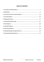
TABLE OF CONTENTS 1. Precautions and Safety Notices 1 2. Specification ...4 3. Front Panel Function Control Description 25 4. Circuit Description ...30 5. Adjusting Procedure ...40 6. Trouble Shooting Flow Chart 51 7. Block Diagrams ...59 8. Schematic Diagrams ...60 9. PCB Layout Diagrams ...65 10. Exploded Diagram And Spare Parts List 69 11. Recommended Spare Parts List 73 ViewSonic Corporation ii Confidential - Do Not Copy VA2016w-2
-
 1
1 -
 2
2 -
 3
3 -
 4
4 -
 5
5 -
 6
6 -
 7
7 -
 8
8 -
 9
9 -
10
-
11
-
12
-
13
-
14
-
15
-
16
-
17
-
18
-
19
-
20
-
21
-
22
-
23
-
24
-
25
-
26
-
27
-
28
-
29
-
30
-
31
-
32
-
33
-
34
-
35
-
36
-
37
-
38
-
39
-
40
-
41
-
42
-
43
-
44
-
45
-
46
-
47
-
48
-
49
-
50
-
51
-
52
-
53
-
54
-
55
-
56
-
57
-
58
-
59
-
60
-
61
-
62
-
63
-
64
-
65
-
66
-
67
-
68
-
69
-
70
-
71
-
72
-
73
-
74
-
75
-
76
-
77
-
78
-
79
 |
 |

ii
ViewSonic Corporation
Confidential - Do Not Copy
VA2016w-2
TABLE OF CONTENTS
1. Precautions and Safety Notices
.........................................................................................
1
2. Specification
.......................................................................................................................
4
3. Front Panel Function Control Description
.....................................................................
25
4. Circuit Description
.............................................................................................................
30
5. Adjusting Procedure
..........................................................................................................
40
6. Trouble Shooting Flow Chart
............................................................................................
51
7. Block Diagrams
................................................................................................................
59
8. Schematic Diagrams
........................................................................................................
60
9. PCB Layout Diagrams
......................................................................................................
65
10. Exploded Diagram And Spare Parts List
........................................................................
69
11. Recommended Spare Parts List
....................................................................................
73