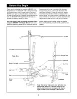
Weider 175 English Manual - Page 9
Front Leg 19 with the Bolt and an M10 Nylon
 |
View all Weider 175 manuals
Add to My Manuals
Save this manual to your list of manuals |
Page 9 highlights
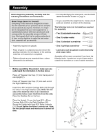
8. Press the Angle Cap (49) onto the indicated end of the Weight Tube (39). Press a 1Ó Round Inner Cap 8 into the opposite end of the Weight Tube. Slide a Weight Stop (53) onto the Weight Tube. Lubricate the M10 x 68mm Bolt (34). Attach the Leg Lever (18) to the indicated hole in the bracket on the Front Leg (19) with the Bolt and an M10 Nylon Locknut (11). Do not overtighten the Nylon Locknut. You must be able to freely pivot the Leg Lever. 53 18 11 49 39 12 19 34 Lubricate 9. Press a 1Ó Round Inner Cap (12) into each end of the Adjustment Tube (29). 9 Insert the Adjustment Tube (29) into the indicated holes in the Uprights (1) in the following manner: First, slide the end with no locking clip partway through the right Upright. Next, slide the end with the 1 locking clip into the left Upright as far as it will go. Finally, rotate the Adjustment Tube until the locking clip snaps into place around the Upright. 12 29 1 Locking Clip 12 10. Press a 1Ó Square Inner Cap (28) into each end of the two Backrest Tubes (27). 10 15 Attach the Backrest Tubes (27) to the Backrest (15) with four M6 x 38mm Screws (4) and four M6 28 Washers (30). Note: Do not tighten the four Screws yet. 28 30 11. Slide an M10 Washer (6) onto the M10 x 155mm Bolt (22). Lubricate the Bolt. Place the Backrest (15) onto the Adjustment Tube (29). Slide the M10 x 155mm Bolt (22) through the right Backrest Tube (27) and then slide a 16mm x 18.5mm Spacer (8) onto the Bolt. 27 11 30 4 4 8 15 Line up the M10 x 155mm Bolt (22) with the hole in the Bench Frame (5) and slide the Bolt through the Frame until the tip is barely visible on the other side. Place a 16mm x 18.5mm Spacer (8) between the Bench Frame and the left Backrest Tube (27) and slide the Bolt through both the Spacer and the Backrest Tube. Secure the Bolt with an M10 Washer (6) and an M10 Nylon Locknut (11). Do not overtighten the Nylon Locknut. You must be able to freely pivot the Backrest. Tighten the four M6 x 38mm Screws (4) used in step 10. Lubricate 22 6 5 27 29 6 11 9
-
 1
1 -
2
-
3
-
 4
4 -
 5
5 -
 6
6 -
 7
7 -
 8
8 -
 9
9 -
 10
10 -
 11
11 -
 12
12 -
 13
13 -
 14
14 -
15
-
16
-
17
-
18
-
19
-
20
-
21
-
22
 |
 |
