Weider 420 Bench English Manual - Page 5
Preparation
 |
View all Weider 420 Bench manuals
Add to My Manuals
Save this manual to your list of manuals |
Page 5 highlights
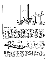
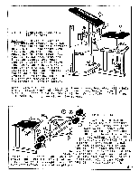
0 0 0 1 0 (r) • . o O .0 le O 0 0 0 • • • O • 2 a C 0 B 3 • • 0 STEP 1 - FRAME ASSEMBLY Lay out all frame pieces: 2 UPRIGHTS (1), U-FRAME (2), and FRONT FRAME (3). To assemble, first align bolt holes on upright bracket with bolt holes on U-FRAME (2). Secure with 2 HEX HEAD BOLTS (A) and 2 LOCK NUTS (B). Repeat to attach opposite UPRIGHT (1). Slide FRONT FRAME (3) toward U-FRAME (2) aligning bolt holes on front frame bracket with bolt holes on u-frame front. Secure with 2 HEX HEAD BOLTS (C) and 2 LOCK NUTS PLASTIC CAP (H) into loWer frame piece of FRONT fRAME (3), and 1 SQUARE PLASTIC CAP (H) into upright frame piece'of FRONT FRAME (3). Tighten all bolts. 1 LOOSEN OR 2 TURN 0 0 REMOVE STEP 2 - BACKREST PREPARATION Note: The lower or attachment end of the BACKREST (5) can be identified quickly by the LONG ANGLE IRONS (8). The LONG ANGLE IRONS (8) will be extended approximately two inches beyond the BACKREST PAD (5). Turn BACKREST (5) over to expose work area. Both LONG ANGLE IRONS (8) have been fastened to BACKREST (5) for shipment. One LONG ANGLE IRON (8) must be loosened in order to assemble BACKREST (5) to front frame pivot rod. The lower MACHINE SCREW (G) must be removed while the upper MACHINE SCREW (G) is only loosened. The LONG ANGLE IRON (8) can now swing freely from the lower end of BACKREST (5). 3 •
-
 1
1 -
 2
2 -
 3
3 -
 4
4 -
 5
5 -
 6
6 -
 7
7
 |
 |
