Weider 420 Bench English Manual - Page 6
Weider 420 Bench Manual
 |
View all Weider 420 Bench manuals
Add to My Manuals
Save this manual to your list of manuals |
Page 6 highlights
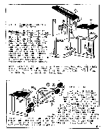
5 Qte 0 • N 0 N 0 0 .0 STEP 3 - CONNECTING BACKREST & 0 SEAT TO FRAME 0 BACKREST: To aid in assembly, first position BACKREST ADJ. BAR (11) over one of the hole patterns 0 0 11 0 ••• • I• I• • I J • on UPRIGHTS (1) and secure with 2 LOCKING PINS (N). With LONG ANGLE IRON (8) free, lower. BACKREST (5) to backrest pivot rod. Slide the secured LONG ANGLE BACKREST PIVOT ROO 0 0 IRON (8) onto one side of pivot 0 rod. Swing the free LONG ANGLE IRON (8) back to its original 0 position and onto the opposite end of the pivot rod. See Detail A. Replace MACHINE SCREW (G) that was removed in Step 2 and tighten all machine screws. 0 SEAT BRACICET • 0 0 F SEAT: With SEAT (6) right-side up, lower to seat brackets. Align bolt holes. Insert 2 MACHINE SCREWS (G) through seat bracket holes into SEAT (6). Insert 1 MACHINE SCREW (F) through bolt hole in front frame into SEAT (6). Tighten all machine screws. 4 CURL BRACKE • 0 v4F 10 J L 0 _ J O 9 STEP 4 - LEG CURL 0 Place LEG CURL (4) between leg curl brackets on front frame and align bolt holes. Secure with HEX HEAD BOLT (D) and LOCK NUT (E). Repeat the following instructions until all PAD BARS (10) and FOAM PADS (9) are in place. First, slide PAD BAR (10) through proper hole in LEG CURL (4) until equal amounts of bar are on both sides of LEG CURL (4). Slide one FOAM PAD (9) unto each end of PAD BAR (10). Insert ROUND PLASTIC CAP (J) into each end of PAD BAR (10). Insert SQUARE PLASTIC CAP (H) into end of LEG CURL (H). Insert ROUND PLASTIC CAP (K) into weight pin on LEG CURL (4). Place COVER CAP (L) over rear extended piece of weight pin. 4
-
 1
1 -
 2
2 -
 3
3 -
 4
4 -
 5
5 -
 6
6 -
 7
7
 |
 |
