Weider 8620 English Manual - Page 11
Route the Long Cable 23 around the ²V° - parts
 |
View all Weider 8620 manuals
Add to My Manuals
Save this manual to your list of manuals |
Page 11 highlights
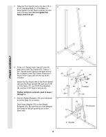
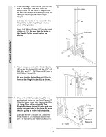
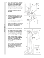
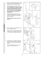
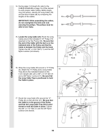
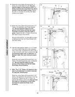
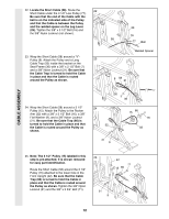
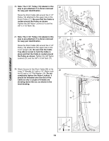
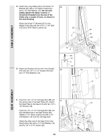
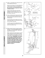
CABLE ASSEMBLY 18. Route the Long Cable (23) around the ÒVÓ- 18 Pulley (6) on the Right Arm (48). Be sure that the Cable is in the groove of the ÒVÓ- Pulley and that the Long Cable Trap (50) is turned to hold the Cable in place. Tighten the 3/8Ó x 2 1/2Ó Bolt (7) and the 3/8Ó Nylon Locknut (not shown). 50 7 6 48 23 19. Route the Long Cable (23) around the 3 1/2Ó Pulley (15) attached to the Pulley Bracket (20). Be sure that the Cable is in the groove of the Pulley and that the Cable Trap (66) is turned to hold the Cable in place. Tighten the 3/8Ó x 2Ó Bolt (12) and the 3/8Ó Nylon Locknut (not shown). Be sure that the 5/16Ó x 5Ó Bolt (68) is properly tightened and that the Pulley Bracket (20) can move freely. 19 68 66 20 12 23 15 20. See the inset drawing. Attach a 3 1/2Ó Pulley 20 (15) and a Cable Trap (66) to the indicated hole in the Long ÒUÓ-Bracket (57) with a 3/8Ó x 2Ó Bolt (12) and a 3/8Ó Nylon Locknut (21). Be sure that the Cable Trap is inside the ÒUÓ- Bracket. Note: This may come pre-assem- bled. 23 23 Route the Long Cable (23) around the 3 1/2Ó Pulley (15) and through the Long ÒUÓ-Bracket (57). Be sure that the Cable is in the groove of the Pulley and that the Cable and Pulley move smoothly. 15 66 12 21 57 21. Note: The 3 1/2Ó Pulley (15) labeled in this 21 step is pre-attached. It is shown removed for easy part identification. 23 15 Bracket 12 Route the Long Cable (23) around the 3 1/2Ó Pulley (15) attached to the bracket on the Top Frame (55). Tighten the 3/8Ó x 2Ó Bolt (12) 55 and the 3/8Ó Nylon Locknut (21). Be sure that the Cable is in the groove of the Pulley and that the Cable and Pulley move 21 smoothly. 11
-
 1
1 -
2
-
3
-
4
-
5
-
 6
6 -
 7
7 -
 8
8 -
 9
9 -
 10
10 -
 11
11 -
 12
12 -
 13
13 -
 14
14 -
 15
15 -
 16
16 -
17
-
18
-
19
-
20
-
21
-
22
-
23
-
24
-
25
 |
 |
