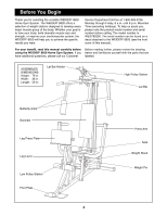
Weider 8620 English Manual - Page 9
Leg Lever 29 to the Rocker Arm 32 - assembly
 |
View all Weider 8620 manuals
Add to My Manuals
Save this manual to your list of manuals |
Page 9 highlights
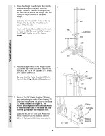
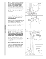
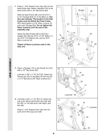
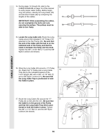
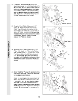
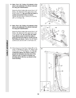
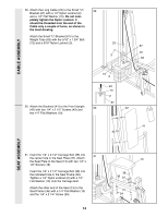
11. Press a 1 3/4Ó Square Inner Cap (44) into the 11 Seat Frame (36). Attach a Bumper (73) to the Seat Frame with a 1/2Ó Tap Screw (65). Slide the Seat Frame (36) onto the 5/16Ó x 2 1/2Ó Carriage Bolts (1) in the Base (4). See the inset drawing. The bracket on the Seat Frame must be behind the Press Frame (17). Hand-tighten a 5/16Ó Nylon Locknut (3) 42 onto each Carriage Bolt. Do not tighten the Nylon Locknuts until the end of this assembly step. 3 Attach the Seat Frame (36) to the Front Upright (42) with two 5/16Ó x 2 3/4Ó Bolts (11), 8 two 5/16Ó Flat Washers (8), and two 5/16Ó Nylon Locknuts (3). 11 Tighten all Nylon Locknuts used in this step now. Bracket 36 17 44 73 36 65 3 ARM ASSEMBLY 12. Attach a Bumper (73) to the Rocker Arm (32) with a 1/2Ó Tap Screw (65). 12 Lubricate a 3/8Ó x 3 1/4Ó Bolt (35). Attach the Rocker arm (32) to the Base (4) with the 3/8Ó x 3 1/4Ó Bolt and a 3/8Ó Nylon Locknut (21). 4 1 73 65 32 21 13. Lubricate a 3/8Ó x 2 1/2Ó Bolt (7). Attach the Leg Lever (29) to the Rocker Arm (32) with the 3/8Ó x 2 1/2Ó Bolt and a 3/8Ó Nylon Jam Nut (33). Press a 1 3/4Ó Square Inner Cap (44) into each end of the Leg Lever (29). 4 LubricateÑ35 13 44 32 7ÑLubricate 33 29 44 9
-
 1
1 -
2
-
3
-
 4
4 -
 5
5 -
 6
6 -
 7
7 -
 8
8 -
 9
9 -
 10
10 -
 11
11 -
 12
12 -
 13
13 -
 14
14 -
15
-
16
-
17
-
18
-
19
-
20
-
21
-
22
-
23
-
24
-
25
 |
 |
