Weider Cjxt3 Master Trainer User Manual - Page 7
Weider Cjxt3 Master Trainer Manual
 |
View all Weider Cjxt3 Master Trainer manuals
Add to My Manuals
Save this manual to your list of manuals |
Page 7 highlights
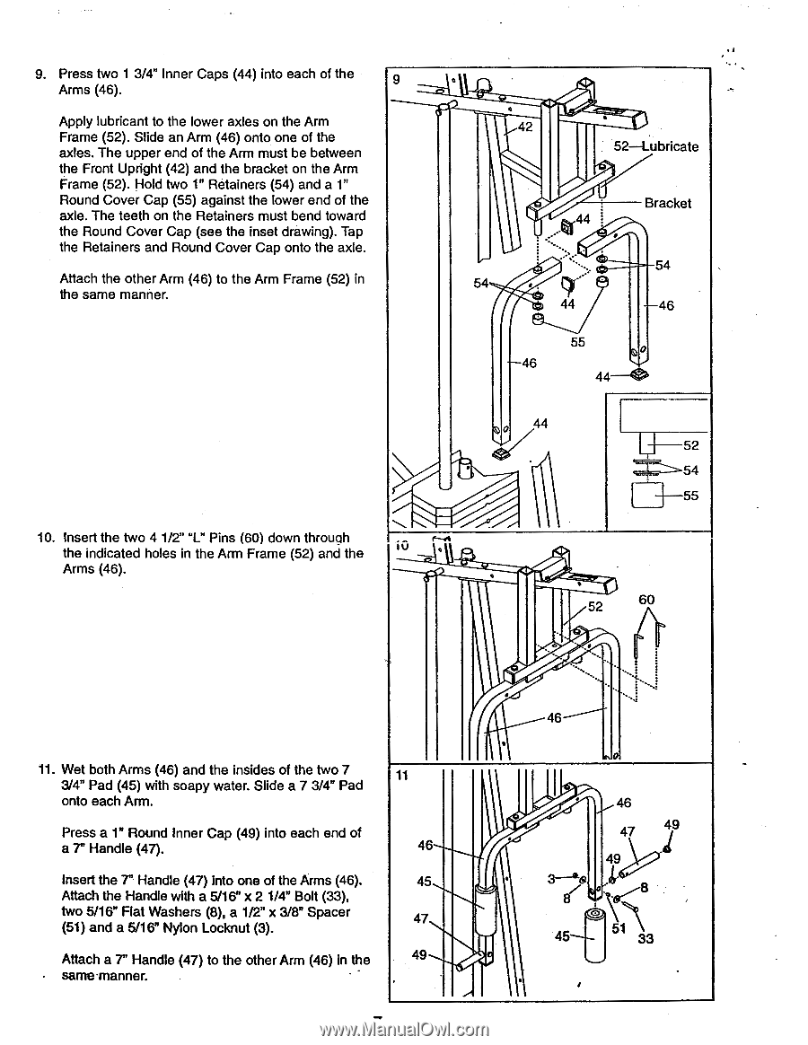
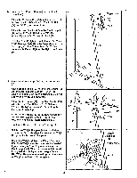
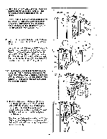
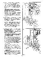
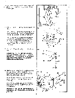
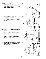
9. Press two 1 3/4" Inner Caps (44) into each of the 9 Arms (46). Apply lubricant to the lower axles on the Arm Frame (52). Slide an Arm (46) onto one of the axles. The upper end of the Arm must be between the Front Upright (42) and the bracket on the Arm Frame (52). Hold two 1" Retainers (54) and a 1" Round Cover Cap (55) against the lower end of the axle. The teeth on the Retainers must bend toward the Round Cover Cap (see the inset drawing). Tap the Retainers and Round Cover Cap onto the axle. Attach the other Arm (46) to the Arm Frame (52) in the same manner. 10. Insert the two 4 1/2" "L" Pins (60) down throuah the indicated holes in the Arm Frame (52) and the 10 Arms (46). 42 52-Lubricate Bracket 44 Ir • 54 54 44 46 55 46 44-0 44 U 52 54 55 • 52 60 11. Wet both Arms (46) and the insides of the two 7 3/4" Pad (45) with soapy water. Slide a 7 3/4" Pad onto each Arm. Press a 1" Round Inner Cap (49) into each end of a 7" Handle (47). Insert the 7" Handle (47) into one of the Arms (46). Attach the Handle with a 5/16" x 2 1/4" Bolt (33), two 5/16" Flat Washers (8), a 1/2" x 3/8" Spacer (51) and a 5/16" Nylon Locknut (3). Attach a 7" Handle (47) to the other Arm (46) in the same•manner. 11 46 45 47 49 46 46 47 49 45
-
 1
1 -
 2
2 -
 3
3 -
 4
4 -
 5
5 -
 6
6 -
 7
7 -
 8
8 -
 9
9 -
 10
10 -
 11
11 -
 12
12 -
13
-
14
-
15
-
16
-
17
-
18
-
19
-
20
-
21
-
22
-
23
-
24
-
25
-
26
-
27
 |
 |