Weider Cjxt3 Master Trainer User Manual - Page 9
Weider Cjxt3 Master Trainer Manual
 |
View all Weider Cjxt3 Master Trainer manuals
Add to My Manuals
Save this manual to your list of manuals |
Page 9 highlights
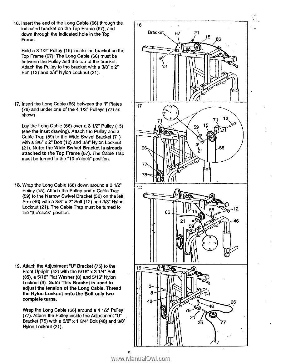
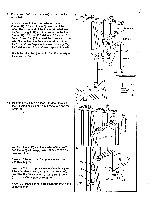
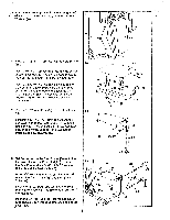
16. Insert the end of the Long Cable (66) through the indicated bracket on the Top Frame (67), and down through the indicated hole in the Top Frame. Hold a 3 1/2" Pulley (15) inside the bracket on the Top Frame (67). The Long Cable (66) must be between the Pulley and the top of the bracket. Attach the Pulley to the bracket with a 3/8" x Bolt (12) and 3/8" Nylon Locknut (21). 16 Bracket 67 ...' 12 21 15 66 . 17. Insert the Long Cable (66) between the "I" Plates (78) and under one of the 4 1/2" Pulleys (77) as shown. Lay the Long Cable (66) over a 3 1/2" Pulley (15) (see the inset drawing). Attach the Pulley and a Cable Trap (59) to the Wide Swivel Bracket (71) with a 3/8" x 2" Bolt (12) and 3/8" Nylon Locknut (21). Note: the Wide Swivel Bracket is already attached to the Top Frame (67). The Cable Trap must be turned to the "10 o'clock" position. 18. Wrap the Long Cable (66) down around a 3 1/2" vulley (15). Attach the Pulley and a Cable Trap (59) to the Narrow Swivel Bracket (58) on the left Arm (46) with a 3/8" x 2" Bolt (12) and 3/8" Nylon Locknut (21). The Cable Trap must be turned to the "3 o'clock" position. 17 12 0 9 'N 3 71 6 ..- o • 71 12 59 15 iiNti 66 77 78 18 c(l 1 66 ..... - • 66 15 58 12 21-4g • 46 59 12 9 *---..3 6 19. Attach the Adjustment "U" Bracket (75) to the 19 Front Upright (42) with the 5/16" x 3 1/4" Bolt (35), a 5/16" Flat Washer (8) and 5/16" Nylon Locknut (3). Note: This Bracket is used to adjust the tension of the Long Cable. Thread the Nylon Locknut onto the Bolt only two complete turns. Wrap the Long Cable (66) around a 4 1/2" Pulley 8 ' • ... 42 66 4 75 A (77). Attach the Pulley inside the Adjustment "U" Bracket (75) with a 3/8" x 1 3/4" Bolt (48) and 3/8" Nylon Locknut (21). 21 35 . - 0
-
 1
1 -
2
-
3
-
 4
4 -
 5
5 -
 6
6 -
 7
7 -
 8
8 -
 9
9 -
 10
10 -
 11
11 -
 12
12 -
 13
13 -
 14
14 -
15
-
16
-
17
-
18
-
19
-
20
-
21
-
22
-
23
-
24
-
25
-
26
-
27
 |
 |