Weider Power Guide X2 User Manual - Page 10
The Cable Trap must
 |
View all Weider Power Guide X2 manuals
Add to My Manuals
Save this manual to your list of manuals |
Page 10 highlights
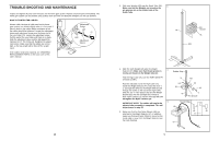
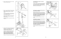
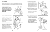
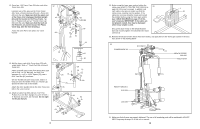
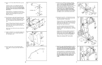
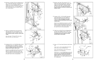
18. Route the Low Cable (70) on the indicated side of 18 the "V" Brace (42). Route the Low Cable into the groove in a 3 1/2" Thin Pulley (4). Attach th ePulley an d a Cable Trap (69) to the LArge Pivot Bracket (52) with a 3/8" x 1 3/4" Bolt (68) and a 3/8" Jam Nut (82). Be sure the Cable Trap is in the 1 o'clock position. 52 68 82 69 4 70 12 9 3 6 42 19. Attach a "U" Bracket (31) to one of the Press 19 Arms (29) with a 3/8" x 2 1/2" Bolt (44), a 3/8" Flat Washer (65), and a 3/8" Nylon Locknut (2). Be sure that the Cable Trap (69) is on the side shown. Attach the other "U" Bracket (31) to the other Press Arm (29) in the same manner. 42 2 31 2 31 29 65 44 29 65 44 20. Lubricate a 5/16" x 2 1/4" Bolt (80). Attach a Small Pivot Bracket (32) to the indicated "U" Bracket (31) with the Bolt and a 5/16" Nylon Locknut (1). Do not overtighten the Nylon; the Small Pivot Bracket must be able to pivot freely. Route the Low Cable (70) up around a 3 1/2" Thin Pulley (4). Attach the Pulley and a Cable Trap (69) to the Small Pivot Bracket (32) with a 3/8" x 1 3/4" Bolt (68) and a 3/8" Jam Nut (82). Be sure the Cable Trap is in the 3 o'clock position. 20 12 9 3 70 69 6 82 4 80-Lubricate 68 32 1 31 10 21. Wrap the Low Cable (70) around the 3 1/2" "V" Pulley (74). Attach the Pulley and a Large Cable Trap (73) to the indicated bracket on the Main Upright (41) with a 3/8" x 2 1/4" Bolt (78) and a 3/8" Jam Nut (82). The Cable Trap must be inside the bracket, and must be secured in the position shown. 21 74 73 78 41 82 22. Lubricate a 5/16" x 2 1/4" Bolt (80). Attach the Small Pivot Bracket (32) to tthe indicated "U" Bracket (31) with the Bolt and a 5/16" Nylon Locknut (1). Do not overtighten the Nylon Locknut; the Small Pivot Bracket must be able to pivot freely. Route the Low Cable (70) up around a 3 1/2" Thin Pulley (4). Attach the Pulley and the Cabel Trap (69) to the Small Pivot Bracket (32) with a 3/8" x 1 3/4" Bolt (68) and a 3/8" Jam Nut (82). Be sure the Cable Trap is in the indicated position. 23. Attach the Low Cable (70) to the indicated bracket on the Main Upright (41) with a 5/16" x 3/4" Bolt (76) and a 5/16" Nylon Locknut (1). Do not overtighten the Nylon Locknut; the Cable must be able to swivel freely. 70 22 4 70 82 80-Lubricate 31 68 32 69 1 23 76 1 41 70 24. Press a 1 1/2" Inner Cap (19) into the Seat Frame 24 (18). Insert a 1/4" x 2 1/4" Carriage Bolt (12) into the centre hole of each Seat Bracket (13). Attach each Seat Bracket (13) to the Seat (17) with two 1/4" x 1/2" Screws (11). Insert the 1/4" x 2 1/4" Carriage Bolts (12) into the Seat Frame (18). The wide end of the Seat (17) must be facing the curved end of the Seat Frame. Tighten two 1/4" Nylon Locknuts (3), with the two 5/16" x 1 1/2" Fender Washers (28), onto the Carriage Bolts. 11 17 Wide End 13 12 11 19 13 11 28 18 3
-
 1
1 -
2
-
3
-
4
-
 5
5 -
 6
6 -
 7
7 -
 8
8 -
 9
9 -
 10
10 -
 11
11 -
 12
12
 |
 |
