Weider Power Guide X2 User Manual - Page 7
Adjustment
 |
View all Weider Power Guide X2 manuals
Add to My Manuals
Save this manual to your list of manuals |
Page 7 highlights
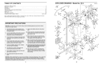
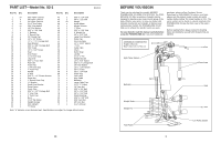
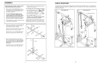
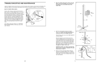
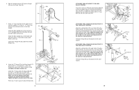
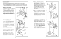
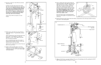
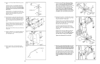
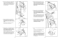
ADJUSTMENT The instructions below describe how each part of the home gym system can be adjusted. Refer to the EXERCISE CHART accompanying this user's manual to see how the home gym system should be set up for each exercise. IMPORTANT: When attaching the lat bar or nylon strap, make sure that the attachments are in the correct starting position for the exercise to be performed. If there is any slack in the cable or chain as an exercise is performed, the effectiveness of the exercise will be reduced. CHANGING THE WEIGHT SETTING To change the weight setting, insert the 4" Weight Pin (50) under one of the Weights (45). Make sure to insert the Weight Pin until the bent end of the Weight Pin is touching the Weights, and turn the bent end 45 downward. The weight setting can be changed from 12.5 pounds (5.675 kg) to 125 pounds (56.75 kg), in increments of 12.5 pounds (5.675 kg). Note: Due to the cables and pulleys, the actual amount of resistance at each exercise station will vary from the weight setting. 50 SWITCHING THE PRESS ARMS TO THE PRESS MODE OR THE BUTTERFLY MODE To perform the BENCH PRESS exercise, insert the two 4 1/2" "L" Pins (61) down through the indicated holes in the Press Frame (33) and the Press Arms (29). Make sure that the "J"-Pin (56) is removed. To perform the BUTTERFLY exercise, remove the two 4 1/2" "L" Pins (61). Insert the "J"-Pin (56) into the Main Upright (41) behind the Press Frame (33). Insert the Pin until it is locked in position around the tubing on the Press Frame. ATTACHING AND REMOVING THE SEAT Set the bracket on the Seat Frame (18) onto the indicated pins on the Main Upright (41). Attach the Seat Frame to the Main Upright with the 5/16" x 2 3/4" Carriage Bolt (14) and the 5/16" Knob (15). For some exercises, the Seat Frame (18) must be removed. First, make sure that the chain is not attached to the leg lever. Next, remove the 5/16" Knob (15) and the 5/16" x 2 3/4" Carriage Bolt (14) from the Seat Frame (18). Lift the Seat Frame off the Main Upright (41). 41 33 56 61 29 41 18 15 Pins 14 14 9. Press two 1 3/4" Inner Caps (24) and two 1" 9 Round Caps (9) into the Press Frame (33). Lubricate the top axle of the Press Frame (33). Place one Press Bushing (54) onto the plate on the Main Upright (41). Set the lubricated axle of the Press Frame into the groove of the Press Bushing. The Press Frame must be turned so the bracket is on the side shown. Place the other Press Bushing (54) on top of the lubricated axle. Attach the Press Cap (53) to the plate on the Main Upright with four 1/4" x 1/2" Screws (11) and four 1/4" Jam Nuts (75). 10. Note: The 3 1/2" Thin Pulley (4), 3/8" x 1 3/4" Bolt (68), and 3/8" Nylon Locknut (2) shown in this step have been pre-attached. Remove the parts from the Main Upright (41). Lay the High Cable (71) in the groove of the 3 1/2" Thin Pulley (4) as shown. Attach the Pulley to the Main Upright (41) with the 3/8" x 1 3/4" Bolt (68) and the 3/8" Nylon Locknut (2). 10 2 75 11 75 53 54 Lubricate 41 11 9 24 33 9 24 Bracket 41 68 4 71 11. Lay the end of the High Cable (71) in the groove of a 3 1/2" Thin Pulley (4). Attach the Pulley to the front of the Main Upright (41) with the 3/8" x 3 1/2" Bolt (51) and a 3/8" Jam Nut (82). Make sure that the rubber stop is on the indicated side of the Pulley. Lay the High Cable (71) in the groove of another 3 1/2" Thin Pulley (4). Attach the Pulley and a Cable Trap (69) to the Main Upright (41) with the 3/8" x 4 1/4" Bolt (77), a 3/8" Flat Washer (65), and a 3/8" Jam Nut (82). Make sure that the Cable Trap is in the 10 o'clock position. Pull down on the High Cable (71) so that all of the slack is in the indicated location. 11 12 10 9 3 6 69 77 65 82 41 4 Pull Down Here 82 51 71 Rubber 4 Stop 7
-
 1
1 -
 2
2 -
 3
3 -
 4
4 -
 5
5 -
 6
6 -
 7
7 -
 8
8 -
 9
9 -
 10
10 -
 11
11 -
 12
12
 |
 |
