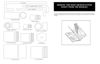
Weider Power Guide X2 User Manual - Page 9
Note: The Large Pivot Bracket 52, the 5/16 x
 |
View all Weider Power Guide X2 manuals
Add to My Manuals
Save this manual to your list of manuals |
Page 9 highlights
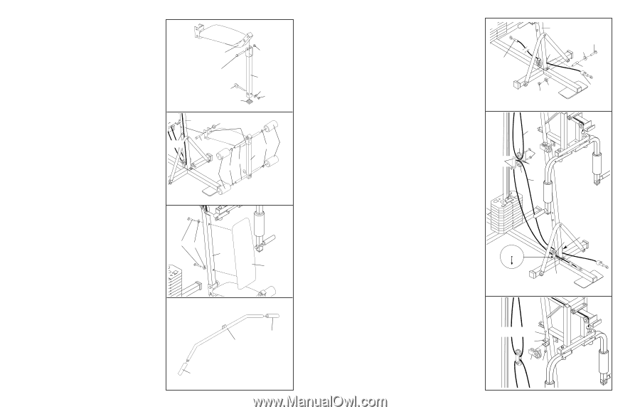
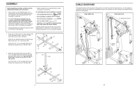
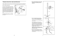
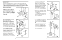
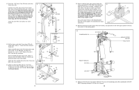
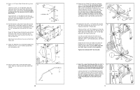
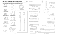
25. Press a 1 1/2" Inner Cap (19) into the Leg Lever (20). Lubricate a 5/16" x 2 1/4" Bolt (80). Attach the Leg Lever (20) to the Seat Frame (18) with the Bolt and a 5/16" Jam Nut (81). Do not overtighten the Jam Nut; the Leg Lever must be able to pivot freely. Insert the 5/16" x 2" Eye Bolt (21) into the Leg Lever (20) from the indicated side. Attach the Eye Bolt with a 5/16" Flat Washer (5) and a 5/16" Nylon Locknut (1). 26. Set the bracket on the Seat Frame (18) onto the indicated pins on the Main Upright (41). Attach the Seat Frame to the Main Upright with the 5/16" x 2 3/4" Carriage Bolt (14) and the 5/16" Knob (15). Press 3/4" Round Caps (10) into the ends of both Pad Tubes (22). Insert one Pad Tube into the Seat Frame (18). Insert the other Pad Tube into the Leg Lever (20). Slide Foam Pads (23) onto the ends of both Pad Tubes (22). 25 18 81 Lubricate-80 20 21 5 19 1 26 41 15 18 Pins 14 23 10 20 22 10 23 27. Attach the Backrest (72) to the Main Upright (41) 27 with the two 1/4" x 2 1/2" Screws (16) and two 1/4" Flat Washers (6). 16 6 41 72 28. Wet the ends of the Lat Bar (60) with soapy 28 water. Slide a 5" Grip (27) onto each end of the Lat Bar. 27 12 27 60 15. Route the Low Cable (70) under the indicated 3 1/2" Thin Pulley (4). Be sure that the rubber stop is on the indicated side of the Pulley. Slide a 5/16" Flat Washer (5) and the 1/2" x 1 1/4" Spacer (66) onto the 5/16" x 3 3/4" Bolt (49). Insert the Bolt into the Main Upright (41), under the indicated Pulley (4). Make sure that the Cable is between the Spacer and the Pulley. Slide another 5/16" Flat Washer (5) onto the Bolt, and tighten a 5/16" Jam Nut (81) onto the Bolt. 15 70 41 4 5 81 49 5 66 Rubber Stop 16. Remove the two 3/8" x 1 3/4" Bolts (68), the two 3/8" Nylon Locknuts (2), and the two 3 1/2" Thin Pulleys (4) from the "I" Plates (48). Hold one of the 3 1/2" Thin Pulleys (4) in the indicated loop of the High Cable (71). Reattach the "I" Plates (48) to the Pulley with a 3/8" x 1 3/4" Bolt (68) and a 3/8" Nylon Locknut (2). Lay the Low Cable (70) over the other 3 1/2" Pulley (4). Reattach the Pulley to the "I" Plates (48) with a 3/8" x 1 3/4" Bolt (68) and a 3/8" Nylon Locknut (2). 16 2 71 4 68 48 4 70 Route the end of the Low Cable (70) under the indicated 3 1/2" Thin Pulley (4), between the Pulley and the Cable Trap (69). Make sure that the Cable Trap is in the 6 o'clock position. Tighten the indicated 3/8" Jam Nut (82). 12 9 3 6 82 4 69 17. Note: The Large Pivot Bracket (52), the 5/16" x 3 1/4" Bolt (43), and the 5/16" Nylon Locknut (1) shown in this step have been pre-attached. Remove the parts from the Main Upright (41). Lubricate the 5/16" x 3 1/4" Bolt (43). Re-attach the Large Pivot Bracket (52) to the Main Upright (41) with the Bolt and the 5/16" Nylon Locknut (1). Do not overtighten the Nylon Locknut; the Large Pivot Bracket must be able to pivot freely. 17 43-Lubricate 41 52 1 9
-
 1
1 -
2
-
3
-
 4
4 -
 5
5 -
 6
6 -
 7
7 -
 8
8 -
 9
9 -
 10
10 -
 11
11 -
 12
12
 |
 |