Weider Pro 125 Bench Uk Manual - Page 6
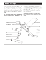
Attach the Backrest Frame to the Main Frame
 |
View all Weider Pro 125 Bench manuals
Add to My Manuals
Save this manual to your list of manuals |
Page 6 highlights
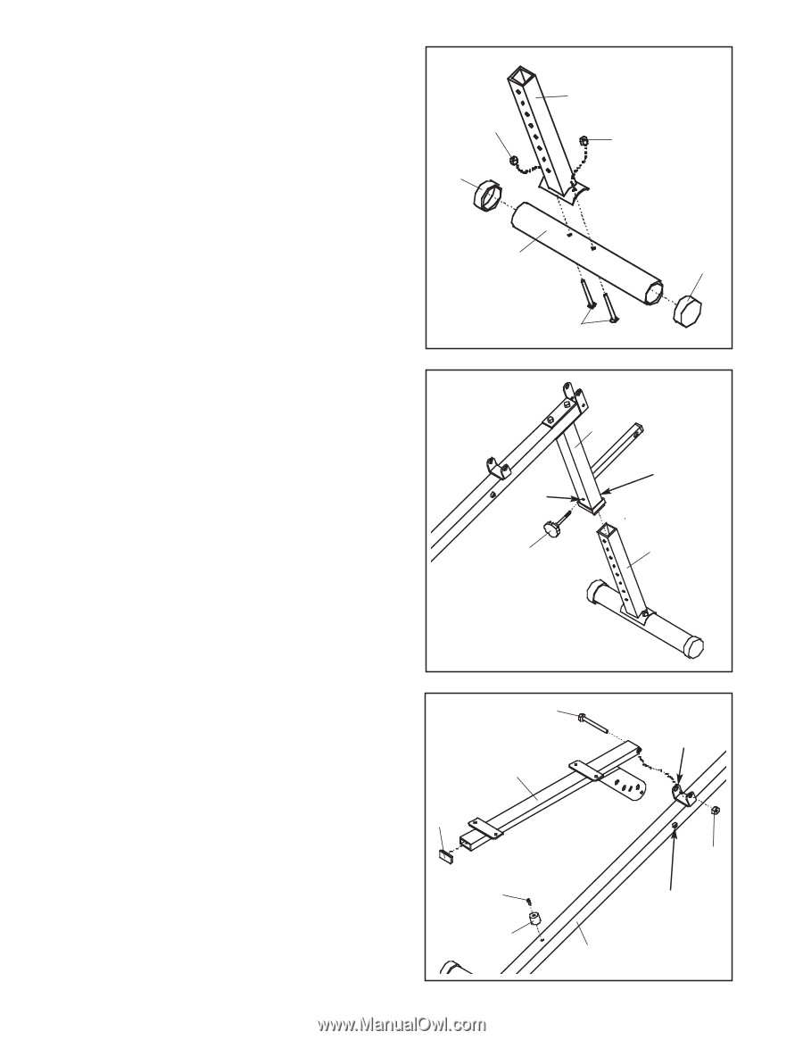
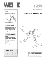
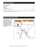
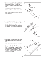
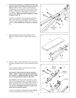
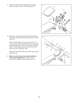
3. Locate the second Stabiliser (2) and note the indentations around the holes. Insert two M10 x 72mm Carriage Bolts (21) through the holes in the Stabiliser so that the bolt heads fit into the indentations. Slide the bracket on the Adjustment Leg (7) onto the two M10 x 72mm Carriage Bolts (21) in the Stabiliser (2). Tighten an M10 Nylon Locknut (18) onto each Bolt. 3 18 10 7 18 Press a 60mm Round Endcap (10) onto each end of the Stabiliser (2). 2 10 4. Slide the Adjustment Leg (7) up into the Leg (6). Line up one of the holes in the Adjustment Leg with 4 the indicated hole in the Leg. Insert the Adjustment Knob (23) into the holes in the Leg (6) and the Adjustment Leg (7). Fully tighten the Adjustment Knob into the indicated welded nut. 21 Hole 23 6 Welded Nut 7 5. Attach a 30mm x 25mm Bumper (26) to the indicated hole in the Main Frame (1) with a Bumper Screw 5 (25). Press a 25mm x 50mm Inner Cap (14) into the indicated end of the Backrest Frame (4). Lubricate an M10 x 80mm Bolt (17) with grease. Hold the opposite end of the Backrest Frame (4) 14 inside the indicated bracket on the Main Frame (1). Attach the Backrest Frame to the Main Frame with the bolt and an M10 Nylon Locknut (18). Do not overtighten the Nylon Locknut; the Backrest Frame must pivot easily. 6 17 4 25 26 1 Bracket 18 Welded Tube
-
 1
1 -
 2
2 -
 3
3 -
 4
4 -
 5
5 -
 6
6 -
 7
7 -
 8
8 -
 9
9 -
 10
10 -
 11
11 -
 12
12 -
13
-
14
-
15
 |
 |