Weider Pro 305 English Manual - Page 8
Weider Pro 305 Manual
 |
View all Weider Pro 305 manuals
Add to My Manuals
Save this manual to your list of manuals |
Page 8 highlights
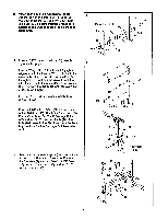
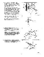
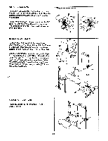
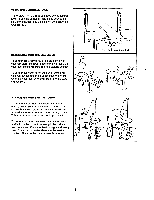
11. Attach the Seat (41) to the Frame (3) with four 11 1/4" x 1/2" Screws (17). Do not tighten the Screws until all four Screws are inserted. Be sure that the Seat is turned as shown. \ .. 41 . Wide End 3 17 i ! 0 12. Attach the Backrest (15) to the Backrest Rail (16) with four 1/4" x 1/2" Screws (17). Do not tighten the Screws until all four Screws are inserted. Attach the Incline Brace (20) to the Backrest Rail (16) with a 5/16" x 3 1/2" Bolt (18) and a 5/16" Nylon Locknut (26). Do not overtighten the Nylon Locknut. 13. Attach the Backrest Rail (16) to the Frame (3) with a 5/16" x 3 1/2" Bolt (18) and a 5/16" Nylon Locknut (26). Rest the end of the Incline Brace (20) in one of the holes in the Frame. 12 15 16 -4,---26 17 18 . L 17 202 13 0 N 20 )6_,..--26 \....- 18 16 Holes 3 14. Press 3/4" Round Caps (50) into the ends of the three Pad Tubes (43). 14 Insert a Pad Tube (43) into the welded tube on the Frame (3). Slide a Foam Pad (44) onto each end of the Pad Tube. Insert two Pad Tubes (43) into the Leg Lever (45). Slide Foam Pads (44) onto the ends of the Pad Tubes. 44 •,- 3 \ . 50 . 45 50 44 0 50 43 8
-
 1
1 -
2
-
 3
3 -
 4
4 -
 5
5 -
 6
6 -
 7
7 -
 8
8 -
 9
9 -
 10
10 -
 11
11 -
 12
12 -
 13
13 -
14
-
15
-
16
-
17
-
18
-
19
 |
 |
