Weider Stepmaster Sm9 English Manual - Page 5
Nylon, Washer, Square
 |
View all Weider Stepmaster Sm9 manuals
Add to My Manuals
Save this manual to your list of manuals |
Page 5 highlights
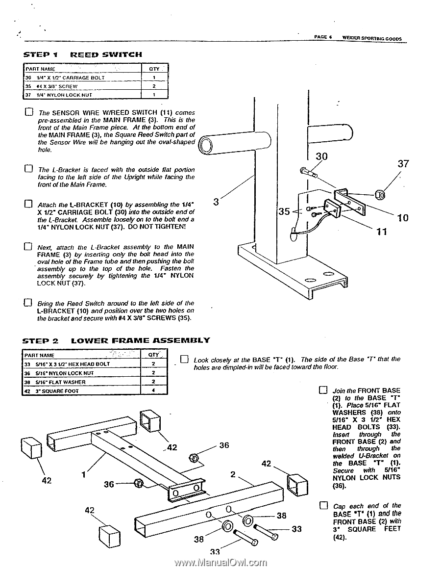
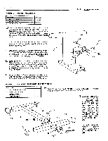
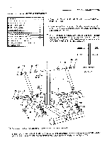
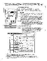
STEP I REED SWITCH i PART NAME 30 1/4" X 1f2" CARRIAGE BOLT 35 W4 X 3/13- SCREW 37 1/4- NYLON LOCK NUT QTY 1 2 1 The SENSOR WIRE W/REED SWITCH (11) comes pre-assembled in the MAIN FRAME (3). This is the front of the Main Frame piece. At the bottom end of the MAIN FRAME (3), the Square Reed Switch part of the Sensor Wire will be hanging out the oval-shaped hole. The L-Bracket is faced with the outside flat portion facing to the left side of the Upright while facing the front of the Main Frame. Attach the L-BRACKET (10) by assembling the 1/4" 3 X 1/2" CARRIAGE BOLT (30) into the outside end of the L-Bracket. Assemble loosely on to the bolt end a 1/4- NYLON LOCK NUT (37). DO NOT TIGHTEN! u Next, attach the L-Bracket assembly to the MAIN FRAME (3) by inserting only the bolt head into the oval hole of the Frame tube and then pushing the bolt assembly up to the top of the hole. Fasten the assembly securely by tightening the 1/4" NYLON LOCK NUT (37). Bring the Reed Switch around to the left side of the L-BRACKET (10) and position over the two holes on the bracket and secure with 114 X 3/8" SCREWS (35). PAGE 6 WEIDER SPORTING GOODS 37 35 STEP 2 LOWER FRAME ASSEMBLY .„.... PART NAME 33 5/16" X 31/2" HEX HEAD BOLT 36 S/16" NYLON LOCK NUT QTY. . 2 2 u Look closely at the BASE (1). The side of the Base "7- that the holes are dimpled-in will be faced toward the floor. 38 5116" FLAT WASHER 2 42 3" SQUARE FOOT 4 CS O O 42 36 42 36 0 0 42 2 Join the FRONT BASE (2) to the BASE (1). Place 5/16" FLAT WASHERS (38) onto 5/16" X 3 1/2 HEX HEAD BOLTS (33). Insert through the FRONT BASE (2) and then through the welded U-Bracket on the BASE "7" (1). Secure with 5/16" NYLON LOCK NUTS (36). 42 0 0 u Cap each end of the 38 BASE "T" (1) and the N FRONT BASE (2) with 33 3" SQUARE FEET 38 (42). 33
-
 1
1 -
 2
2 -
 3
3 -
 4
4 -
 5
5 -
 6
6 -
 7
7 -
 8
8 -
 9
9 -
 10
10 -
 11
11
 |
 |