Weider Stepmaster Sm9 English Manual - Page 9
Electronics Monitor
 |
View all Weider Stepmaster Sm9 manuals
Add to My Manuals
Save this manual to your list of manuals |
Page 9 highlights
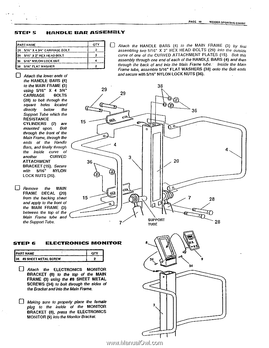
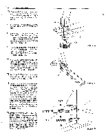
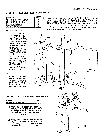
STEP S HANDLE BAR ASSEMBLY PAGE 10 WEIOER SPORTING GOODS PART NAME 28 5/16" X 4 3/4" CARRIAGE BOLT 29 6/16" X 2" HEX HEAD BOLT 36 . 5/16" NYLON LOCK NUT 38 6/16" FLAT WASHER Attach the lower ends of the HANDLE BARS (4) to the MAIN FRAME (3) using 5/16" X 4 3/4" CARRIAGE BOLTS (28) to bolt through the square holes located directly below the Support Tube which the RESISTANCE CYLINDERS (7) are mounted upon. Bolt through the front of the Main Frame, through the ends of the Handle Bars, and finally through the inside curve of another CURVED ATTACHMENT BRACKET (15). Secure with 5/16" NYLON LOCK NUTS (36). QTY ID Attach the HANDLE BARS (4) to the MAIN FRAME (3) by first 2 assembling two 5/16" X 2" HEX HEAD BOLTS (29) into the outside 2 curve of one of the CURVED ATTACHMENT PLATES (15). Bolt this 4 assembly through one end of each of the HANDLE BARS (4) and then 2 through the back of and into the Main Frame tube. Inside the Main Frame tube, assemble 5/16" FLAT WASHERS (38) onto the Bolt ends and secure with 5/16" NYLON LOCK NUTS (36). 38 29 • 29 15 0 4 3 36 36 4 20 Remove the MAIN FRAME DECAL (20) from the backing sheet 15 and apply to the front of the MAIN FRAME (3) between the top of the Main Frame tube and the Support Tube. 0 7 0 7 SUPPORT TUBE 28 28 STEP 6 ELECTRONICS MONITOR PART NAME 34 48 SHEET METAL SCREW QTY 2 Mach the ELECTRONICS MONITOR BRACKET (8) to the top of the MAIN FRAME (3) using the 118 SHEET METAL SCREWS (34) to bolt through the sides of the Bracket andinto the Main Frame. Making sure to properly place the female plug to the inside of the MONITOR BRACKET (8), press the ELECTRONICS MONITOR (9) into the Monitor Bracket. 34 0 or 34 0
-
 1
1 -
2
-
3
-
 4
4 -
 5
5 -
 6
6 -
 7
7 -
 8
8 -
 9
9 -
 10
10 -
 11
11
 |
 |