Weider Stepmaster Sm9 English Manual - Page 8
&MU
 |
View all Weider Stepmaster Sm9 manuals
Add to My Manuals
Save this manual to your list of manuals |
Page 8 highlights
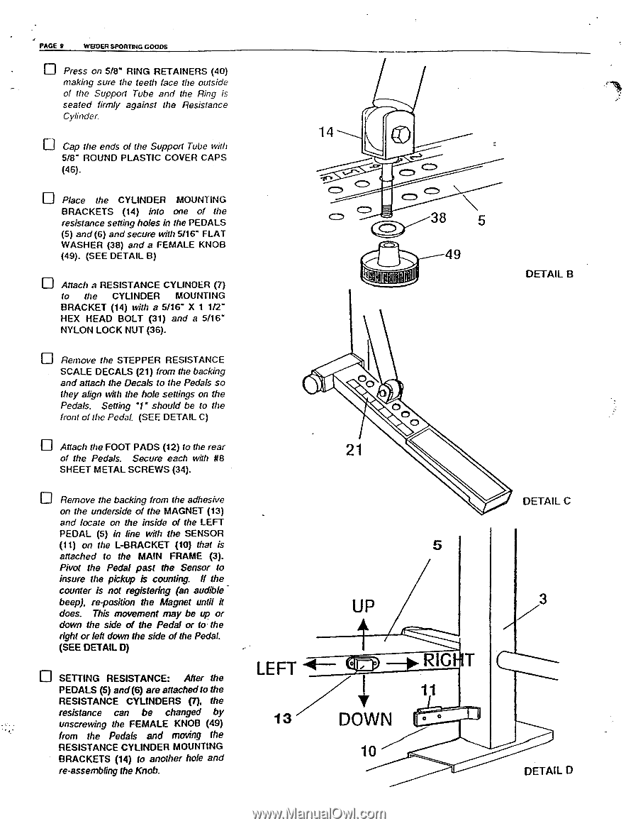
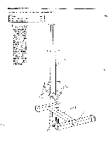
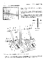
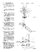
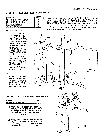
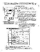
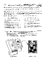
J PAGE 9 WEIDER SPORTING GOODS Press on 5/8" RING RETAINERS (40) making sure the teeth face the outside of the Support Tube and the Ring is seated firmly against the Resistance Cylinder. Cap the ends of (he Support Tube with 5/8" ROUND PLASTIC COVER CAPS (46). 0 Place the CYLINDER MOUNTING BRACKETS (14) into one of the resistance setting holes in the PEDALS (5) and(6) and secure with 5/16" FLAT WASHER (38) and a FEMALE KNOB (49). (SEE DETAIL B) Mach a RESISTANCE CYLINDER (7) to the CYLINDER MOUNTING BRACKET (14) with a 5/16" X 1 1/2" HEX HEAD BOLT (31) and a 5/16" NYLON LOCK NUT (36). Remove the STEPPER RESISTANCE SCALE DECALS (21) from the backing and attach the Decals to the Pedals so they align with the hole settings on the Pedals. Setting '1" should be to the front of the Pedal (SEE DETAIL C) Attach the FOOT PADS (12) to the rear of the Pedals. Secure each with 118 SHEET METAL SCREWS (34). Remove the backing from the adhesive on the underside of the MAGNET (13) and locate on the inside of the LEFT PEDAL (5) in line with the SENSOR (11) on the L-BRACKET (10) that is attached to the MAIN FRAME (3). Pivot the Pedal past the Sensor to insure the pickup is counting. If the counter is not registering (an audible beep), re-position the Magnet until it does. This movement may be up or down the side of the Pedal or to the right or left down the side of the Pedal. (SEE DETAIL 0) SETTING RESISTANCE: After the PEDALS (5) and(6) are attachedto the RESISTANCE CYLINDERS (7), the resistance can be changed by unscrewing the FEMALE KNOB (49) from the Pedals and moving the RESISTANCE CYLINDER MOUNTING BRACKETS (14) to another hole and re-assembling the Knob. 14 OI CD 38 5 49 21 5 UP A LEFT •44--- 0 • -*RIG T 11 1 3 ' DOWN &MU 10 DETAIL B DETAIL C 3 DETAIL 0
-
 1
1 -
2
-
 3
3 -
 4
4 -
 5
5 -
 6
6 -
 7
7 -
 8
8 -
 9
9 -
 10
10 -
 11
11
 |
 |