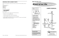
Weslo 600 Instruction Manual - Page 6
the Lat Bar. Press a 1 Round Inner Cap 12
 |
View all Weslo 600 manuals
Add to My Manuals
Save this manual to your list of manuals |
Page 6 highlights
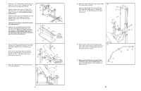
2. Press two 1 1/2" Square Inner Caps (6) into the Frame (51). Press a 1 1/2" Square Inner Cap (6) into each of the Stabilisers (49, 50). Attach the Frame (51) to the "H" Frame (52) with two 5/16" x 2 1/4" Bolts (32) and two 5/16" Nylon Locknuts (1). Do not tighten the Nylon Locknuts yet. Attach the Frame (51) to the Stabilisers (49, 50) with two 5/16" x 5 1/2" Bolts (5), the two Stabiliser Plates (65), and two 5/16" Nylon Locknuts (1). Tighten all of the Nylon Locknuts (1) used in this step and step 1. 3. Attach the Left and Right Backrest Brackets (59, 60) to the Backrest (54) with four 1/4" x 5/8" Screws (7). Make sure that the Brackets are oriented so the indicated holes are on the end shown. Note: The Screws may come pre-inserted into the Backrest. 4. Tap 3/4" Round Inner Caps (16) into the indicated ends of the Adjustment Tube (61). Insert the Adjustment Tube into the "H" Frame (52) as shown. Attach the Left and Right Backrest Brackets (59, 60) to the Frame (51) with the 5/16" x 4" Bolt (9), two 1/2" x 7/8" Spacers (8), and a 5/16" Nylon Locknut (1). 5. Attach the Seat (56) to the Frame (51) with two 1/4" x 5/8" Screws (7). 2 32 52 6 1 51 50 49 5 3 7 59 60 54 1 65 65 6 7 Holes Toward Wide End Of Backrest 4 16 52 61 59 60 16 1 51 8 9 5 56 51 7 6 18. Attach the Lower Cable (30) to the Upper Cable 18 (37) with a Cable Clip (39). Wrap the Lower Cable (30) around a Pulley (36). Attach the Pulley to the "U" Bracket (33) with a 3/8" x 1 1/2" Bolt (34) and a 3/8" Nylon Locknut (15). 37 39 30 36 15 19. Wet the ends of the Lat Bar (42) with soapy 19 water. Slide a Foam Grip (21) onto each end of the Lat Bar. Press a 1" Round Inner Cap (12) into each end of the Lat Bar. 33 34 21 12 42 20. Make sure that all parts are properly tightened before you use the weight bench. The use of all remaining parts will be explained on pages 12 to 14. 21 12 11
-
 1
1 -
 2
2 -
 3
3 -
 4
4 -
 5
5 -
 6
6 -
 7
7 -
 8
8 -
 9
9 -
 10
10
 |
 |
