Weslo 600 Instruction Manual - Page 7
end of a Short Pad Tube 47. Insert the Pad
 |
View all Weslo 600 manuals
Add to My Manuals
Save this manual to your list of manuals |
Page 7 highlights
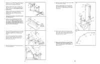
16. Slide the Lat Tower (40) into the Frame (51). 16 The Lat Tower must be turned as shown. Attach the Lat Tower to the Frame with a 5/16" x 2" Bolt (10), two 5/16" Washers (3), and a 5/16" Nylon Locknut (1). Fully tighten the Knob (29) into the Frame. 40 17. Locate the Upper Cable (37), which has a ball on one end. Insert the Upper Cable through the top of the Lat Tower (40) as shown. Attach a Pulley (36) inside the Lat Tower (40) with a 3/8" x 1 1/2" Bolt (34) and a 3/8" Nylon Locknut (15). Make sure that the ball is on the indicated side of the Pulley and that the Upper Cable (37) is between the Pulley and the welded rod. Attach the other Pulley (36) inside the Lat Tower (40) in the same way. Attach the Upper Cable (37) to the Weight Carriage (41) with a Cable Clip (39). 29 10 17 Welded Rod 34 Ball 36 40 41 1 3 51 15 37 36 39 10 6. Press 1 1/2" Square Inner Caps (6) into both ends of the Leg Lever (45). Attach the 14" Weight Tube (46) to the Leg Lever (45) with a 5/16" x 2" Bolt (10), two 5/16" Washers (3), a 1/2" x 5/16" Spacer (24), and a 5/16" Nylon Locknut (1). Press the 1" Round Angle Cap (66) onto the indicated end of the Weight Tube (46). Tap a 1" Round Inner Cap (12) into other end of the Weight Tube. Slide a Weight Stop (13) onto the Weight Tube. 7. Lubricate the 3/8" x 2 1/2" Bolt (14). Attach the Leg Lever (45) to the Frame (51) with the Bolt and a 3/8" Nylon Locknut (15). 6 45 66 1 3 24 6 3 46 10 12 13 6 7 51 15 45 14 8. Press a 3/4" Round Inner Cap (16) into each end of a Short Pad Tube (47). Insert the Pad Tube into one of the holes in the Leg Lever (45). Slide a 5 1/2" Foam Pad (18) onto each end of the Pad Tube. Repeat for the other Short Pad Tube (47). Press a 3/4" Round Inner Cap (16) into each end of the Long Pad Tube (48). Insert the Pad Tube into the indicated hole in the Frame (51). Slide a 6" Foam Pad (20) onto each end of the Pad Tube. 8 51 20 20 16 18 48 47 45 16 18 9. Press two Square Outer Bushings (28) onto the 9 "H" Frame (52). Wet the inside of a Foam Grip (21) with soapy water. Slide the Foam Grip onto a Weight Rest (55). Press a 1" Round Inner Cap (12) into the Weight Rest. Slide the Weight Rest into one side of the "H" Frame. Align one of the small holes in the Weight Rest with the small hole in the "H" Frame (52). Insert a Medium Lock Pin (22) through the Weight Rest and the "H" Frame. Assemble the other Weight Rest (55) in the same way. 7 12 21 55 28 22 22 52
-
 1
1 -
 2
2 -
 3
3 -
 4
4 -
 5
5 -
 6
6 -
 7
7 -
 8
8 -
 9
9 -
 10
10
 |
 |
