Weslo 850 Instruction Manual - Page 3
Part List-model No. Wetl85061, Warning, Save These Instructions
 |
View all Weslo 850 manuals
Add to My Manuals
Save this manual to your list of manuals |
Page 3 highlights
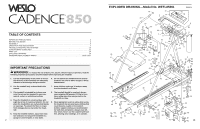
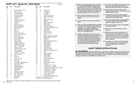
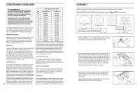
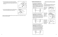
PART LIST-Model No. WETL85061 Key Qty. Description No. Key Qty. No. Description R0697A 1 2 Handrail w/Foam Grip 2 3 3/8" x 1" Bolt 3 1 Console Housing 4 1 60" Wire Harness 5* 1 Console Assembly 6 7 Console Screw 7 1 Pot Wire 8 1 Console Cable Loom 9 1 SAFEKEYTM/Clip 10 2 Foam Grip 11 1 Upright 12 1 Motor Swivel Bolt 13 1 Motor Mount Bracket 14 1 Motor Swivel Nut 15 2 Motor Bolt 16 1 Motor 17 2 Motor Nut 18 1 Motor Tension Bolt 19 1 Motor Tension Washer 20 1 Star Washer 21 1 Motor Tension Nut 22 2 Incline Leg Washer 23 4 Hood Anchor 24 7 Anchor Screw 25 1 Upright Pivot Nut 26 2 Upright Pivot Washer 27 1 Upright Cable Loom 28 1 3/8" x 1 1/2" Washer 29 2 Rubber Cushion 30 1 Power Cord-Not used 31 1 Circuit Breaker 32 1 Upright Pivot Bolt 33 1 Grommet-Not used 34 2 Frame Endcap 35 13 Screw 36 2 Incline Pin 37 2 Incline Leg Cap 38 2 Incline Leg 39 1 Belt Guide 40 1 Front Roller Adjustment Bolt 41 3 Adjustment Washer 42 1 Safety Cover 43 1 Front Roller/Pulley 44 1 Walking Platform 45 1 Walking Belt 46 2 Foot Rail 47 1 Pulley/Flywheel/Fan 48 2 5/16" Flange Nut 49 2 5/16" x 2 3/4" Bolt 50 2 5/16" Washer 51 1 Controller 52 1 Choke 53 13 Small Screw 54 2 4" Cable Tie 55 2 8" Cable Tie 56 1 Tie Holder 57 2 Motor Pivot Bushing 58 1 Motor Pivot Sleeve 59 1 Frame 60 2 Rear Leg Endcap 61 1 Magnet 62 1 Roller Ground Wire 63 1 Right Endcap 64 2 Wrench Clip 65 1 3/16" Allen Wrench 66 2 Rear Roller Adjustment Bolt 67 1 Left Endcap 68 1 Rear Roller 69 8 Platform Screw 70 2 Incline Leg Plug 71 1 Hood 72 1 Reed Switch Extension Wire 73 1 Reed Switch/Sensor Wire 74 1 Motor Belt 75 3 Cage Nut 76* 1 Motor/Pulley/Flywheel/Fan 77 1 Battery Cover 78 1 Potentiometer 79 1 Speed Control 80 2 3/8" Washer 81 1 Interface Board 82 1 Electronics Plate 83 1 Electronics Plate Grommet 84 1 Filter 85 4 Plastic Stand-Off 86 3 Plastic Washer 87 1 Filter Bracket 88 2 Ground Screw 89 2 Ground Star Washer 90 2 Ground Nut 91 4 Filter Screw 92 1 Motor/Controller Wire 93 1 Receptical # 1 14" White Wire, Twisted # 1 10" White Wire, 2 Female # 1 8" White Wire, Male/Female-not used # 1 8" Black Wire, 2 Female # 1 4" Black Wire, 2 Female # 1 8" Blue Wire, Twisted # 1 4" Green Ground Wire # 1 User's Manual # 1 4" Black Wire, Male/Female * Includes all parts shown in the box. # Indicates a non-illustrated part. Specifications are subject to change without notice. See the back cover for information about ordering replace14 ment parts. 10. When connecting the power cord (see HOW TO PLUG IN THE POWER CORD on page 7), plug the power cord into an earthed circuit. When replacing the fuse, on ASTA approved BS1362 type should be fitted to the fuse carrier. A 13 amp fuse should be used. No other appliance should be on the same circuit. 15. Never start the treadmill whilst you are standing on the walking belt. Always hold the handrails whilst exercising on the treadmill. 16. The treadmill is capable of high speeds. Adjust the speed in small increments to avoid sudden jumps in speed. 11. If you need an extension cord, use only a 14-gauge cord of 5 feet (1,50 m) or less in length. 12. Keep the power cord away from heated surfaces. 17. To reduce the possibility of the treadmill overheating, do not operate the treadmill continuously for longer than 1 hour. 18. Never leave the treadmill unattended whilst it is running. Always remove the SAFEKEY when the treadmill is not in use. 13. Never move the walking belt whilst the power is turned off. Do not operate the treadmill if the power cord or plug is damaged, or if the treadmill is not working properly. (See BEFORE YOU BEGIN on page 4 if the treadmill is not working properly.) 14. Always unplug the power cord before performing the maintenance and adjustment procedures described in this manual. Never remove the motor hood unless instructed to do so by an authorised service representative. Servicing other than the procedures in this manual should be performed by an authorised service representative only. 19. Inspect and tighten all parts of the treadmill every three months. 20. Never drop or insert any object into any opening. 21. The pulse sensor is not a medical device. Various factors, including the user's movement, may affect the accuracy of heart rate readings. The pulse sensor is intended only as an exercise aid in determining heart rate trends in general. 22. To change the incline level of the treadmill, refer to the instructions on page 9. Do not use the treadmill with the incline pins removed. SAVE THESE INSTRUCTIONS WARNING: Before beginning this or any exercise program, consult your physician. This is especially important for persons over the age of 35 or persons with pre-existing health problems. Read all instructions before using. ICON assumes no responsibility for personal injury or property damage sustained by or through the use of this product. 3
-
 1
1 -
 2
2 -
 3
3 -
 4
4 -
 5
5 -
 6
6 -
 7
7 -
 8
8
 |
 |
