Weslo Cadence 4500 Owners Manual - Page 10
Model
 |
View all Weslo Cadence 4500 manuals
Add to My Manuals
Save this manual to your list of manuals |
Page 10 highlights
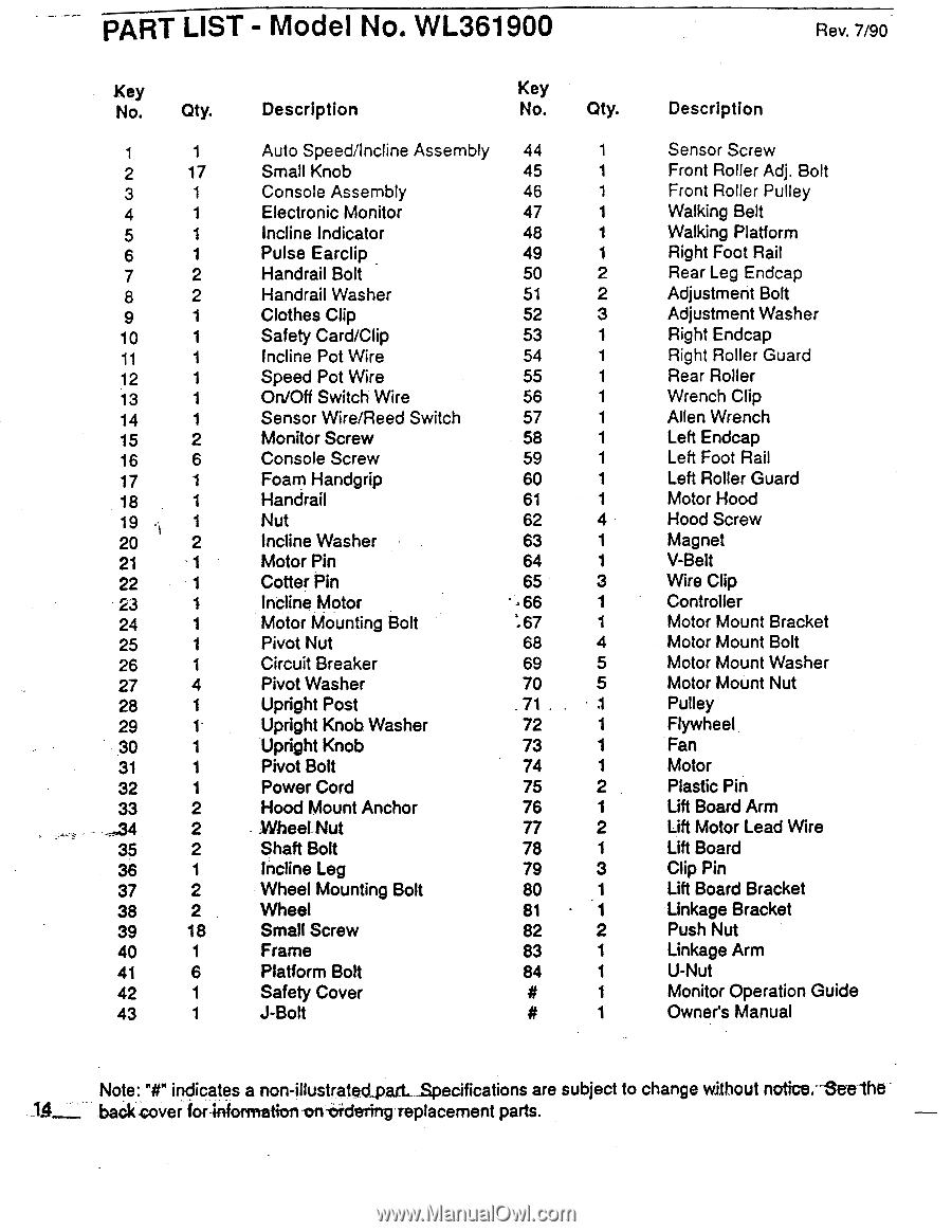
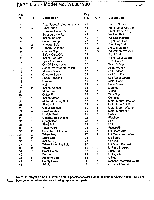
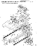
PART LIST - Model No. WL361900 Rev. 7/90 Key No. Qty. 1 1 2 17 3 1 4 1 5 1 6 1 7 2 8 2 9 1 10 1 11 1 12 1 13 1 14 1 15 2 16 6 17 1 18 1 19 • 1 20 2 21 -1 22 1 23 1 24 1 25 1 26 1 27 4 28 1 29 1 30 1 31 1 32 1 33 2 - „34 2 35 2 36 1 37 2 38 2 39 18 40 1 41 6 42 1 43 1 Description Key No. Qty. Auto Speed/Incline Assembly 44 1 Small Knob 45 1 Console Assembly 46 1 Electronic Monitor 47 1 Incline Indicator 48 1 Pulse Earclip _ 49 1 Handrail Bolt 50 2 Handrail Washer 51 2 Clothes Clip 52 3 Safety Card/Clip 53 1 Incline Pot Wire 54 1 Speed Pot Wire 55 1 On/Off Switch Wire 56 1 Sensor Wire/Reed Switch 57 1 Monitor Screw 58 1 Console Screw 59 1 Foam Handgrip 60 1 Handrail 61 1 Nut 62 4 Incline Washer 63 1 Motor Pin 64 1 Cotter Pin 65 3 Incline Motor • -66 1 Motor Mounting Bolt :67 1 Pivot Nut 68 4 Circuit Breaker 69 5 Pivot Washer 70 5 Upright Post 71 1 Upright Knob. Washer 72 1 Upright Knob 73 1 Pivot Bolt 74 1 Power Cord 75 2 Hood Mount Anchor 76 1 .Wheel Nut 77 2 Shaft Bolt 78 1 Incline Leg 79 3 Wheel Mounting Bolt 80 1 Wheel 81 • 1 Small Screw 82 2 Frame 83 1 Platform Bolt 84 1 Safety Cover 1 J-Bolt 1 Description Sensor Screw Front Roller Adj. Bolt Front Roller Pulley Walking Belt Walking Platform Right Foot Rail Rear Leg Endcap Adjustment Bolt Adjustment Washer Right Endcap Right Roller Guard Rear Roller Wrench Clip Allen Wrench Left Endcap Left Foot Rail Left Roller Guard Motor Hood Hood Screw Magnet V-Belt Wire Clip Controller Motor Mount Bracket Motor Mount Bolt Motor Mount Washer Motor Mount Nut Pulley Flywheel Fan Motor Plastic Pin Lift Board Arm Lift Motor Lead Wire Lift Board Clip Pin Lift Board Bracket Linkage Bracket Push Nut Linkage Arm U-Nut Monitor Operation Guide Owner's Manual Note: "#" indicates a non-illustratectpaLt .S.pecifications are subject to change without notice.--See'the It_ back -cover for-information on-Oidering-replacement parts.
-
 1
1 -
2
-
3
-
4
-
 5
5 -
 6
6 -
 7
7 -
 8
8 -
 9
9 -
 10
10 -
 11
11 -
 12
12
 |
 |