Weslo Pursuit 625s Uk Manual - Page 6
Assembly - battery
 |
View all Weslo Pursuit 625s manuals
Add to My Manuals
Save this manual to your list of manuals |
Page 6 highlights
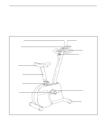
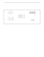
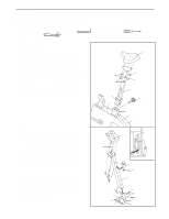
ASSEMBLY Place all parts of the PURSUIT 625s in a cleared area and remove the packing materials. Do not dispose of the packing materials until assembly is completed. Assembly requires the included allen wrench adjustable spanners . , a phillips screwdriver , and two 1. Press the Side Shield Cover (30) onto the Left and Right Side Shields (1, 2). 1 Insert the Seat Post (20) into the Frame (15). Press the Seat Post Bushing (23) into the Frame. Next, align one of the holes in the Seat Post with the hole in the Frame. Insert the Seat Knob (29) into the Frame and the Seat Post, and tighten the Seat Knob into the Frame. Make sure to insert the Seat Knob through one of the holes in the Seat Post; do not insert the Seat Knob under the Seat Post. Attach the Seat (19) to the Seat Post (20) with three M8 Nylon Locknuts (21) and three M8 Split Washers (53). Note: The Nylon Locknuts and the Split Washers may be pre-attached to the bottom of the Seat. 53 21 23 30 19 53 21 20 29 2. The Console (7) requires two 1,5V batteries (not included). Alkaline batteries are recommended. Refer to the inset drawing. Locate the battery compartment on the back of the Console. Press two batteries into the battery compartment. Make sure that the negative ends of the batteries (marked "-") are touching the springs in the battery compartment. Insert the console wire through the Handlebar Post (14). Connect the console wire to the Reed Switch Wire (54). Attach the Console (7) to the Handlebar Post with four M4 x 16mm Screws (9). Carefully slide the Handlebar Post (14) onto the Frame (15). Be careful to avoid pinching the wires inside the Handlebar Post. Attach the Handlebar Post with three M10 x 25mm Button Screws (8) and three M10 Split Washers (31). Attach the Knob Housing (12) to the Handlebar Post (14) with an M4 x 16mm Screw (9). 2 Console Wire 9 54 31 8 15 1 2 7 7 Batteries 12 9 14 8 31 8 15 6
-
 1
1 -
 2
2 -
 3
3 -
 4
4 -
 5
5 -
 6
6 -
 7
7 -
 8
8 -
 9
9 -
 10
10 -
 11
11 -
 12
12 -
13
-
14
-
15
-
16
 |
 |
