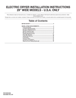
Whirlpool EED4100WQ Installation Instructions - Page 5
Warning - electric dryer
 |
View all Whirlpool EED4100WQ manuals
Add to My Manuals
Save this manual to your list of manuals |
Page 5 highlights
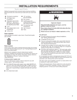
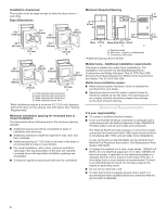
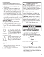
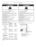
Electrical Connection To properly install your dryer, you must determine the type of electrical connection you will be using and follow the instructions provided for it here. ■■ If local codes do not permit the connection of a neutral ground wire to the neutral wire, see "Optional 3-wire connection" section. ■■ This dryer is manufactured ready to install with a 3-wire electrical supply connection. The neutral ground wire is permanently connected to the neutral conductor (white wire) within the dryer. If the dryer is installed with a 4-wire electrical supply connection, the neutral ground wire must be removed from the external ground connector screw (green screw), and secured under the neutral terminal (center or white wire) of the terminal block. When the neutral ground wire is secured under the neutral terminal (center or white wire) of the terminal block, the dryer cabinet is isolated from the neutral conductor. ■■ A 4-wire power supply connection must be used when the dryer is installed in a location where grounding through the neutral conductor is prohibited. Grounding through the neutral is prohibited for (1) new branch-circuit installations, (2) mobile homes, (3) recreational vehicles, and (4) areas where local codes prohibit grounding through the neutral conductors. If using a power supply cord: Use a UL listed power supply cord kit marked for use with clothes dryers. The kit should contain: ■■ A UL listed 30-amp power supply cord, rated 120/240 volt minimum. The cord should be type SRD or SRDT and be at least 4 ft. (1.22 m) long. The wires that connect to the dryer must end in ring terminals or spade terminals with upturned ends. ■■ A UL listed strain relief. If your outlet looks like this: 4-wire receptacle (14-30R) Then choose a 4-wire power supply cord with ring or spade terminals and UL listed strain relief. The 4-wire power supply cord, at least 4 ft. (1.22 m) long, must have 4 10-gauge solid copper wires and match a 4-wire receptacle of NEMA Type 14-30 R. The ground wire (ground conductor) may be either green or bare. The neutral conductor must be identified by a white cover. If your outlet looks like this: 3-wire receptacle (10-30R) Then choose a 3-wire power supply cord with ring or spade terminals and UL listed strain relief. The 3-wire power supply cord, at least 4 ft. (1.22 m) long, must have 3 10-gauge solid copper wires and match a 3-wire receptacle of NEMA Type 10-30R. If connecting by direct wire: Power supply cable must match power supply (4-wire or 3-wire) and be: ■■ Flexible armored cable or nonmetallic sheathed copper cable (with ground wire), protected with flexible metallic conduit. All current-carrying wires must be insulated. ■■ 10-gauge solid copper wire (do not use aluminum). ■■ At least 5 ft. (1.52 m) long. Install Leveling Legs WARNING Excessive Weight Hazard Use two or more people to move and install dryer. Failure to do so can result in back or other injury. 1. To avoid damaging the floor, use a large flat piece of cardboard from the dryer carton. Place cardboard under the entire back edge of the dryer. See illustration. 2. Firmly grasp the body of the dryer (not the top or console panel). Gently lay the dryer on the cardboard. See illustration. 3. Examine leveling legs. Find the diamond marking. 4. Screw the legs into the leg holes by hand. Use a wrench to finish turning the legs until the diamond marking is no longer visible. 5. Place a carton corner post under each of the 2 dryer back corners. Stand the dryer up. Slide the dryer on the corner posts until it is close to its final location. Leave enough room to connect the exhaust vent. 5
-
 1
1 -
 2
2 -
 3
3 -
 4
4 -
 5
5 -
 6
6 -
 7
7 -
 8
8 -
 9
9 -
 10
10 -
 11
11 -
12
-
13
-
14
-
15
-
16
 |
 |
