Whirlpool EED4100WQ Installation Instructions - Page 7
Style 1: Power supply cord strain relief, Style 2: Direct wire strain relief, wire connection: Power
 |
View all Whirlpool EED4100WQ manuals
Add to My Manuals
Save this manual to your list of manuals |
Page 7 highlights
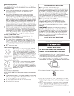
3. Install strain relief. Style 1: Power supply cord strain relief ■■ Remove the screws from a 3/4" (19 mm) UL listed strain relief (UL marking on strain relief). Put the tabs of the two clamp sections (C) into the hole (B) below the terminal block opening so that one tab is pointing up (A) and the other is pointing down (D), and hold in place. Tighten strain relief screws just enough to hold the two clamp sections (C) together. ■■ Put direct wire cable through the strain relief. The strain relief should have a tight fit with the dryer cabinet and be in a horizontal position. Tighten strain relief screw against the direct wire cable. A B C D ■■ Put power supply cord through the strain relief. Be sure that the wire insulation on the power supply cord is inside the strain relief. The strain relief should have a tight fit with the dryer cabinet and be in a horizontal position. Do not further tighten strain relief screws at this point. 4. Now complete installation following instructions for your type of electrical connection: 4-wire (recommended) 3-wire (if 4-wire is not available) 4-wire connection: Power supply cord IMPORTANT: A 4-wire connection is required for mobile homes and where local codes do not permit the use of 3-wire connections. A B F Style 2: Direct wire strain relief ■■ Unscrew the removable conduit connector (A) and any screws from a 3/4" (19 mm) UL listed strain relief (UL marking on strain relief). Put the threaded section of the strain relief through the hole (B) below the terminal block opening. Reaching inside the terminal block opening, screw the removable conduit connector onto the strain relief threads (C). CD E G A. 4-wire receptacle (NEMA type 14-30R) B. 4-prong plug C. Ground prong D. Neutral prong E. Spade terminals with upturned ends F. 3/4" (19 mm) UL listed strain relief G. Ring terminals 1. Remove center, silver-colored terminal block screw (B). 2. Remove neutral ground wire (E) from external ground conductor screw (A). A A B B C E 7
-
 1
1 -
 2
2 -
 3
3 -
 4
4 -
 5
5 -
 6
6 -
 7
7 -
 8
8 -
 9
9 -
 10
10 -
 11
11 -
 12
12 -
13
-
14
-
15
-
16
 |
 |
