Whirlpool GEW9250PT Use and Care Guide - Page 11
wire connection: Direct wire, Optional 3-wire connection
 |
View all Whirlpool GEW9250PT manuals
Add to My Manuals
Save this manual to your list of manuals |
Page 11 highlights
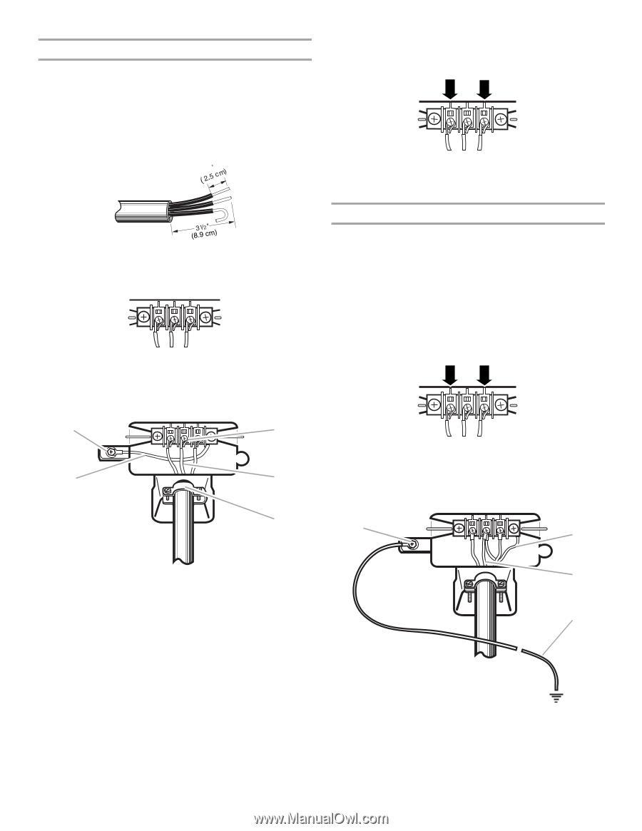
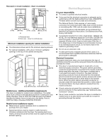
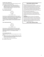
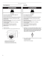
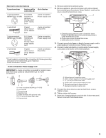
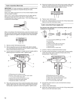
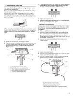
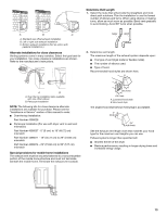
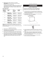
3-wire connection: Direct wire Use where local codes permit connecting cabinet-ground conductor to neutral wire. Direct wire cable must have 5 ft (1.52 m) of extra length so dryer can be moved if needed. Strip 3¹⁄₂" (8.9 cm) of outer covering from end of cable. Strip insulation back 1" (2.5 cm). If using 3-wire cable with ground wire, cut bare wire even with outer covering. Shape ends of wires into a hook shape. 1 When connecting to the terminal block, place the hooked end of the wire under the screw of the terminal block (hook facing right), squeeze hooked end together and tighten screw. See example below. 1. Loosen or remove center terminal block screw. 2. Place the hooked end of the neutral wire (white or center wire) of power supply cable under the center screw of terminal block (hook facing right). Squeeze hooked end together. Tighten screw. A C B D E 3. Place the hooked ends of the other power supply cable wires under the outer terminal block screws (hooks facing right). Squeeze hooked ends together. Tighten screws. 4. Tighten strain relief screws. 5. Insert tab of terminal block cover into slot of dryer rear panel. Secure cover with hold-down screw. Optional 3-wire connection Use for direct wire or power supply cord where local codes do not permit connecting cabinet-ground conductor to neutral wire. 1. Remove center terminal block screw. 2. Remove appliance ground wire (green with yellow stripes) from external ground conductor screw. Connect appliance ground wire and the neutral wire (white or center wire) of power supply cord/cable under center, silver-colored terminal block screw. Tighten screw. 3. Connect the other wires to outer terminal block screws. Tighten screws. 4. Tighten strain relief screws. 5. Insert tab of terminal block cover into slot of dryer rear panel. Secure cover with hold-down screw. 6. Connect a separate copper ground wire from the external ground conductor screw to an adequate ground. A B A. External ground conductor screw C B. Neutral grounding wire (green/yellow) C. Center silver-colored terminal block screw D. Neutral wire (white or center wire) E 1.9 cm) UL listed strain relief D A. External ground conductor screw B. Neutral grounding wire (green/yellow) C. Neutral wire (white or center wire) D. Grounding path determined by a qualified electrician 11
-
 1
1 -
2
-
3
-
4
-
5
-
 6
6 -
 7
7 -
 8
8 -
 9
9 -
 10
10 -
 11
11 -
 12
12 -
 13
13 -
 14
14 -
 15
15 -
 16
16 -
17
-
18
-
19
-
20
-
21
-
22
-
23
-
24
 |
 |