Whirlpool GEW9250PT Use and Care Guide - Page 9
wire connection: Power supply cord
 |
View all Whirlpool GEW9250PT manuals
Add to My Manuals
Save this manual to your list of manuals |
Page 9 highlights
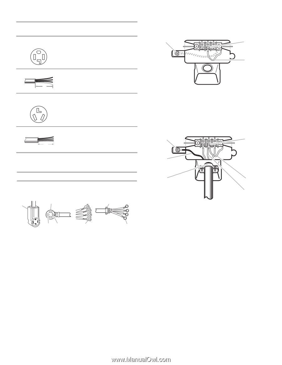
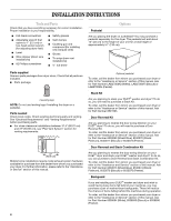
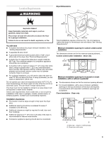
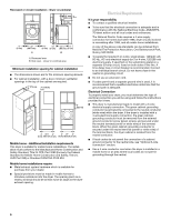
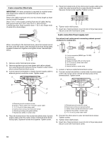
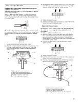
Electrical Connection Options If your home has: And you will be connecting to: Go to Section 4-wire receptacle (NEMA Type 14-30R) A UL listed, 120/240 volt minimum, 30 amp, dryer power supply cord* 4-wire connection: Power supply cord 4-wire direct 5" (12.7 cm) A fused disconnect or circuit breaker box* 4-wire connection: Direct Wire 3-wire receptacle (NEMA type 10-30R) A UL listed, 120/240 volt minimum, 30 amp, dryer power supply cord* 3-wire connection: Power supply cord 3-wire direct 3½" (8.9 cm) A fused disconnect or circuit breaker box* 3-wire connection: Direct Wire 1. Remove center terminal block screw. 2. Remove appliance ground wire (green with yellow stripes) from external ground conductor screw. Fasten it under center, silver-colored terminal block screw. A B C A. External ground conductor screw - Dotted line shows position of NEUTRAL ground wire before being moved to center terminal block screw B. Center silver-colored terminal block screw C. Green/yellow wire of harness 3. Connect ground wire (green or bare) of power supply cord to external ground conductor screw. Tighten screw. 4. Connect neutral wire (white or center wire) of power supply cord under center screw of the terminal block. A D *If local codes do not permit the connection of a frame-grounding conductor to the neutral wire, go to "Optional 3-wire Connection" section. 4-wire connection: Power supply cord IMPORTANT: A 4-wire connection is required for mobile homes and where local codes do not permit the use of 3-wire connections. B F A CD E G A. 4-wire receptacle (NEMA type 14-30R) B. 4-prong plug C. Ground prong D. Neutral prong E. Spade terminals with upturned ends F. ¾" (1.9 cm) UL listed strain relief G. Ring terminals B C E F A. External ground conductor screw B. Green or bare copper wire of power supply cord C 1.9 cm) UL listed strain relief D. Center silver-colored terminal block screw E. Neutral grounding wire (green/yellow) F. Neutral wire (white or center wire) 5. Connect the other wires to outer terminal block screws. Tighten screws. 6. Tighten strain relief screws. 7. Insert tab of terminal block cover into slot of dryer rear panel. Secure cover with hold-down screw. 9
-
 1
1 -
2
-
3
-
 4
4 -
 5
5 -
 6
6 -
 7
7 -
 8
8 -
 9
9 -
 10
10 -
 11
11 -
 12
12 -
 13
13 -
 14
14 -
15
-
16
-
17
-
18
-
19
-
20
-
21
-
22
-
23
-
24
 |
 |