Whirlpool RF265LXTS Installation Instructions
Whirlpool RF265LXTS Manual
 |
View all Whirlpool RF265LXTS manuals
Add to My Manuals
Save this manual to your list of manuals |
Whirlpool RF265LXTS manual content summary:
- Whirlpool RF265LXTS | Installation Instructions - Page 1
30" (76 CM) FREESTANDING ELECTRIC RANGES Table of Contents RANGE SAFETY 1 INSTALLATION REQUIREMENTS 2 Tools and Parts 2 Location Requirements 2 Electrical Requirements 3 INSTALLATION INSTRUCTIONS 4 Unpack Range 4 Install Anti-Tip Bracket 5 Electrical Connection - U.S.A. Only 6 Verify Anti - Whirlpool RF265LXTS | Installation Instructions - Page 2
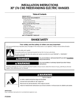
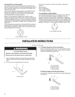
Gather the required tools and parts before starting installation. Read and follow the instructions provided with any tools listed here. Tools needed s Tape measure s ³⁄₈" drive ratchet s Flat-blade screwdriver s ¼" nut driver s Level s Hammer s Hand or electric drill s Wrench or pliers s Marker - Whirlpool RF265LXTS | Installation Instructions - Page 3
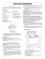
) stainless steel electric shock. Check with a qualified electrician or service instructions provided for it here. s Range must be connected to the proper electrical voltage and frequency as specified on the model/serial number rating plate. The model/serial number rating plate is located on the oven - Whirlpool RF265LXTS | Installation Instructions - Page 4
receptacle (14-50R) INSTALLATION INSTRUCTIONS Unpack Range WARNING Excessive Weight Hazard 3. On Ranges Equipped with Storage Drawers: Remove shipping materials, tape and protective film from range. Remove oven racks and parts package from inside oven. 2. Do not remove the shipping base at - Whirlpool RF265LXTS | Installation Instructions - Page 5
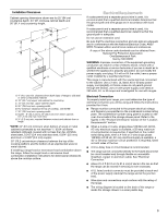
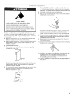
mounting holes through your type of floor covering. Before moving range, slide range onto shipping base, cardboard or hardboard. 1. Remove template from the anti-tip bracket kit (found inside the oven cavity) or from the back of this manual. 2. Place template on the floor in cabinet opening so that - Whirlpool RF265LXTS | Installation Instructions - Page 6
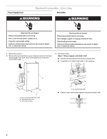
grounded outlet. Failure to follow these instructions can result in death, fire, or electrical shock. Electrical Shock Hazard Disconnect power before servicing. Use 8 gauge copper or 6 gauge aluminum wire. Electrically ground range. Failure to follow these instructions can result in death, fire, or - Whirlpool RF265LXTS | Installation Instructions - Page 7
the ground-link away from the range so that it does not contact the range. A. Removable retaining nut B. Strain relief s Tighten strain relief screw against the flexible conduit. 4. Complete installation following instructions for your type of electrical connection: 4-wire (recommended) 3-wire (if - Whirlpool RF265LXTS | Installation Instructions - Page 8
screws. 5. Replace terminal block cover. Direct Wire Installation: Copper or Aluminum Wire This range may be connected directly to the fuse disconnect or circuit breaker box. Depending on your electrical supply, make the required 3-wire or 4-wire connection. 1. Strip outer covering back 3" (7.6 cm - Whirlpool RF265LXTS | Installation Instructions - Page 9
guides. range back so rear range oven. Place level on rack and check levelness of range, first side to side; then front to back. A. Insert wire under screw clamp. B. Hex washer head screw 3. Securely tighten the hex washer head screws to 35 lbs-in. (4.0 N-m) minimum torque to make a proper electrical - Whirlpool RF265LXTS | Installation Instructions - Page 10
and oven. See the Use and Care Guide for specific instruction on range operation. If range does not operate, check the following: s Household fuse is intact and tight; or circuit breaker has not tripped. s Range is plugged into an outlet. s Electrical supply is connected. s See "Troubleshooting" in - Whirlpool RF265LXTS | Installation Instructions - Page 11
Left edge ANTI-TIP BRACKET TEMPLATE Cut on dotted lines and place the left edge against the left side cabinet and the top edge against the rear wall. Top edge 11 - Whirlpool RF265LXTS | Installation Instructions - Page 12
9762996A © 2006. All rights reserved. 8/06 Printed in U.S.A.
-
 1
1 -
 2
2 -
 3
3 -
 4
4 -
 5
5 -
 6
6 -
 7
7 -
8
-
9
-
10
-
11
-
12
 |
 |
INSTALLATION INSTRUCTIONS
30" (76 CM) FREESTANDING ELECTRIC RANGES
RANGE SAFETY
IMPORTANT:
Save installation instructions for local electrical inspector's use.
9762996A
Table of Contents
RANGE SAFETY
..............................................................................
1
INSTALLATION REQUIREMENTS
................................................
2
Tools and Parts
............................................................................
2
Location Requirements
................................................................
2
Electrical Requirements
...............................................................
3
INSTALLATION INSTRUCTIONS
..................................................
4
Unpack Range
..............................................................................
4
Install Anti-Tip Bracket
.................................................................
5
Electrical Connection - U.S.A. Only
.............................................
6
Verify Anti-Tip Bracket Location
..................................................
9
Level Range
..................................................................................
9
Complete Installation
..................................................................
10
Moving the Range
......................................................................
10
ANTI-TIP BRACKET TEMPLATE
...............................................
11
You can be killed or seriously injured if you don't immediately
You
can be killed or seriously injured if you don't follow
All safety messages will tell you what the potential hazard is, tell you how to reduce the chance of injury, and tell you what can
happen if the instructions are not followed.
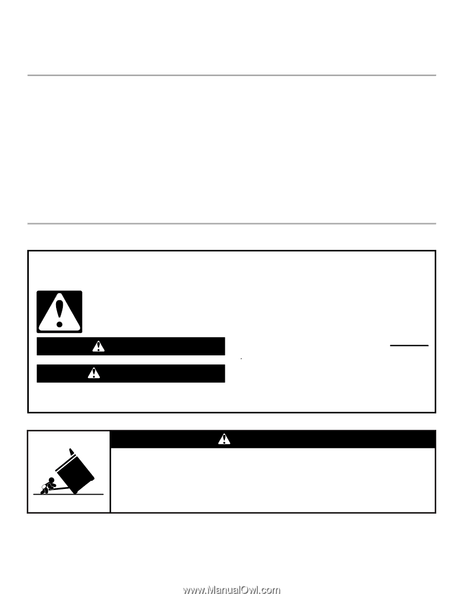
Your safety and the safety of others are very important.
We have provided many important safety messages in this manual and on your appliance. Always read and obey all safety
messages.
This is the safety alert symbol.
This symbol alerts you to potential hazards that can kill or hurt you and others.
All safety messages will follow the safety alert symbol and either the word “DANGER” or “WARNING.”
These words mean:
follow instructions.
instructions.
DANGER
WARNING
WARNING
Tip Over Hazard
A child or adult can tip the range and be killed.
Connect anti-tip bracket to rear range foot.
Reconnect the anti-tip bracket, if the range is moved.
Failure to follow these instructions can result in death or serious burns to children and adults.