Whirlpool RF265LXTS Installation Instructions - Page 7
wire connection: Power supply cord
 |
View all Whirlpool RF265LXTS manuals
Add to My Manuals
Save this manual to your list of manuals |
Page 7 highlights
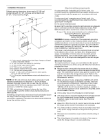
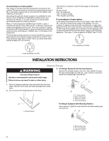
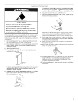
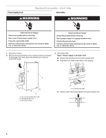
Style 2: Direct wire strain relief s Remove the knockout as needed for the flexible conduit connection. s Assemble a UL listed conduit connector in the opening. A B 4-wire connection: Power supply cord Use this method for: s New branch-circuit installations (1996 NEC) s Mobile homes s Recreational vehicles s In an area where local codes prohibit grounding through the neutral 1. Remove the ground-link screw from the range frame. Save the ground link screw and cup washer. Bend the ground-link away from the range so that it does not contact the range. A. Removable retaining nut B. Strain relief s Tighten strain relief screw against the flexible conduit. 4. Complete installation following instructions for your type of electrical connection: 4-wire (recommended) 3-wire (if 4-wire is not available) Electrical Connection Options If your home has: And you will be Go to Section: connecting to: 4-wire receptacle (NEMA type 14-50R) A UL listed, 250-volt minimum, 40-amp, range power supply cord 4-wire connection: Power supply cord 4-wire direct 5" (12.7 cm) 3-wire receptacle (NEMA type 10-50R) A fused disconnect or circuit breaker box A UL listed, 250-volt minimum, 40-amp, range power supply cord 4-wire connection: Direct wire 3-wire connection: Power supply cord 3-wire direct 1" (2.5 cm) 3" (7.6 cm) A fused disconnect or circuit breaker box 3-wire connection: Direct wire C B A A. Ground-link screw B. Cup washer C. Ground-link bent away from range 2. Connect the green ground wire from the power supply cord to the range using the ground-link screw and cup washer. The ground wire must be attached first and must not contact any other terminal. 3. Use a ¼" nut driver to remove the hex washer head screws from the terminal blocks. 4. Connect the neutral (center) wire to the center terminal connector using one of the hex washer head screws. Securely tighten screw for proper electrical connection. E D F C B G H A I A. Line 1 B. Green ground wire C. Ground-link screw D. Hex washer head screw E. Silver-colored terminal block screw F. Ground-link G. Neutral (center) wire H. Line 2 I. UL listed strain relief and 40- or 50-amp range power supply cord 5. Connect the other 2 wires (lines 1 and 2) to the outer aluminum terminal blocks. 6. Securely tighten screws for proper electrical connection. 7. Tighten strain relief screws. 8. Replace terminal block cover. 7
-
 1
1 -
 2
2 -
 3
3 -
 4
4 -
 5
5 -
 6
6 -
 7
7 -
 8
8 -
 9
9 -
 10
10 -
 11
11 -
 12
12
 |
 |
